Plunger type flow pulsation generator

A flow pulsation, plunger type technology, applied in the direction of fluid flow, piston pump, machine/engine, etc., can solve the problem of fixed pulsation amplitude

Inactive Publication Date: 2009-04-08
XI AN JIAOTONG UNIV
View PDF3 Cites 20 Cited by
  • Summary
  • Abstract
  • Description
  • Claims
  • Application Information

AI Technical Summary

Problems solved by technology

However, the diameter of the piston cylinder and the stroke of

Method used


Image

  • Plunger type flow pulsation generator
  • Plunger type flow pulsation generator
  • Plunger type flow pulsation generator

Examples


Embodiment Construction

[0020] The present invention will be described in further detail below in conjunction with the accompanying drawings.

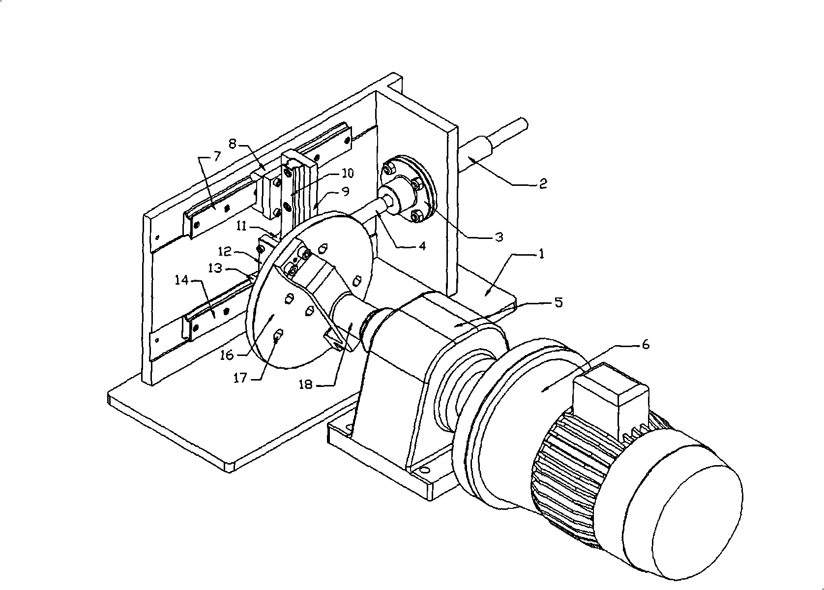
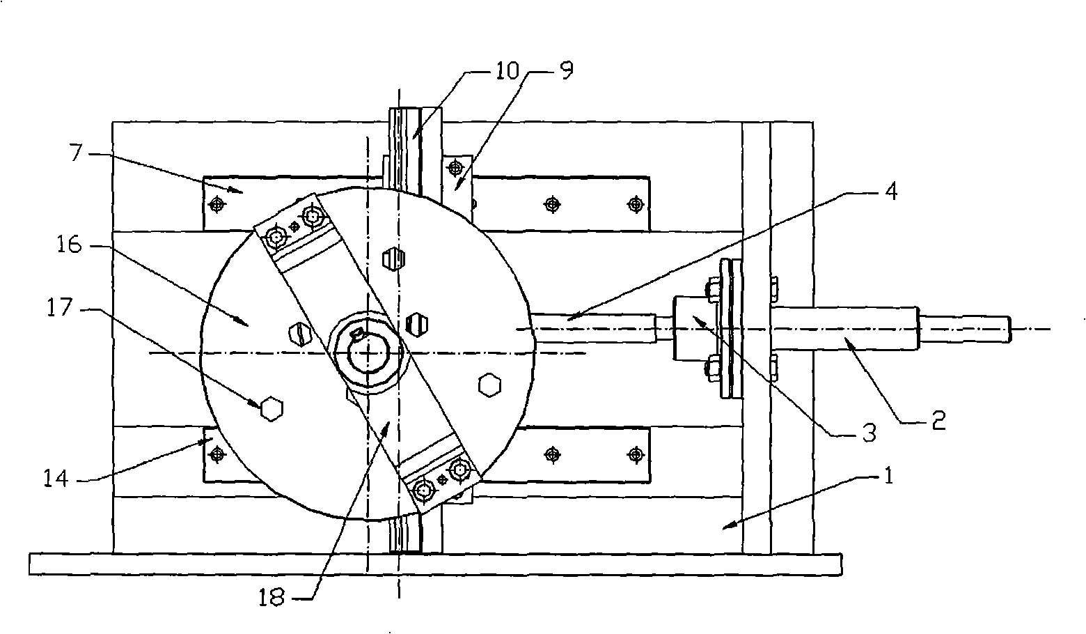
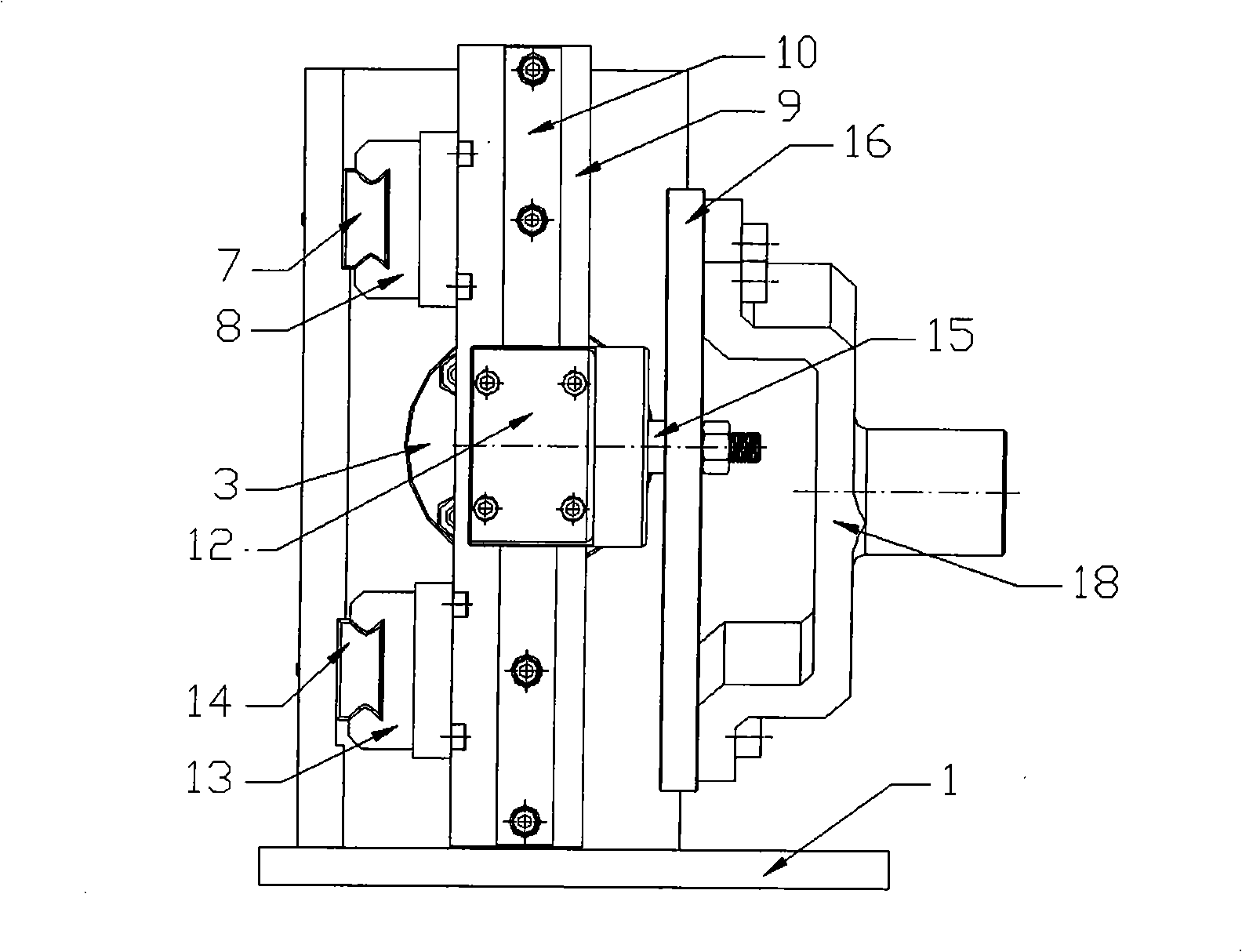
[0021] Referring to Fig. 1(a), Fig. 1(b), Fig. 1(c) and Fig. 1(d), the guiding linear guide rails 7, 14 are fixed on the side wall of the base 1 . The guide rail base 9 is fixed together with the guide sliders 8,13 on the guide linear guide rails 7,14 by screws. The front end of the propulsion guide rail base 9 is connected with the end of the plunger 4 . The cylinder barrel 2 and the sealing end cover 3 matched at the front end of the plunger 4 are fixed on the front end of the base 1 . The propulsion linear guide rail 10 is fixed on the guide rail base surface of the propulsion guide rail base 9 . The propelling slide block 11 on the propelling linear guide rail 10 is connected with the slide block base 12 with the bearing groove. One end of the propulsion shaft 15 is connected with the propulsion shaft 15 through the bearing 19 in the bearing groove, an...


PUM


Abstract

The invention discloses a plunger-typed flow flutter generator, which comprises a rotary table provided with a positioning hole, a propeller shaft, a promoting linear guideway group, a guidance linear guideway group, a plunger, a cylinder, a sealing end cover, a motor, a speed reducer, a frequency converter and the like. The motor drives the rotary table to rotate; the propeller shaft which is fixed on the rotary table and the promoting linear guideway group convert a circular motion into a reciprocating linear simple harmonic motion of the plunger in the cylinder. A plunger cylinder is connected into a flow pipeline by a tee joint; a certain amount of main pipeline fluid is absorbed in or extruded out of the cylinder; and a sine flutter is superimposed on the main flow. The frequency converter changes the rotating speed of a stepping motor and can regulate the period of the flutter. The rotating radius of the propeller shaft which is fixed on the rotary table is regulated so as to change the stroke of the plunger; in addition, plunger suites with different diameters can be replaced; the combination of the two types can change the pumping capacity of the plunger cylinder, thus obtaining the flutter with different amplitudes. The plunger-typed flow flutter generator can generate standard sine flow output with different flutter amplitudes and continuously changing periods.

Description

technical field [0001] The invention relates to the field of flow control in pipelines, in particular to a plunger-type flow pulsation generator for generating pulsating flow in pipelines with adjustable amplitude and period. Background technique [0002] There are a large number of two-phase flow instabilities in nuclear reactors and boiler power plants, one of which is flow pulsation. In addition, the contraction of the human heart also produces rhythmic fluctuations in blood flow in the arteries. In order to analyze the effects of two-phase flow instabilities in industry and to simulate heart pumping in medical research, it is necessary to generate pulsating flow in experimental piping. The conventional flow pulsation generation method is generally to add an auxiliary pump controlled by a frequency converter after the main pump in the pipeline. When the speed of the main pump is constant, the frequency converter is used to change the speed of the auxiliary pump, so that...

Claims


Application Information

Patent Timeline
IPC IPC(8): F15C3/16F15D1/00F04B9/02
Inventor 苏光辉赵大卫张友佳秋穗正王章立
Owner XI AN JIAOTONG UNIV
Why Eureka
Try Eureka