Microelectronic device with heating electrodes

A technology of microelectronic devices and heating arrays, applied in chemical/physical/physicochemical processes, chemical instruments and methods, chemical/physical processes, etc., can solve problems such as limiting the possible accuracy of temperature control

Active Publication Date: 2009-04-08
KONINKLIJKE PHILIPS ELECTRONICS NV
View PDF7 Cites 9 Cited by
  • Summary
  • Abstract
  • Description
  • Claims
  • Application Information

AI Technical Summary

Problems solved by technology

[0004] A problem with microelectronic devices having an array of heating elements and associated local drive units (e.g. current sources) is that variations in the characteristics of the electronic elements due to manufacturing tolerances etc. severely limit the possible accuracy of temperature control

Method used


Image

  • Microelectronic device with heating electrodes
  • Microelectronic device with heating electrodes
  • Microelectronic device with heating electrodes

Examples


Embodiment Construction

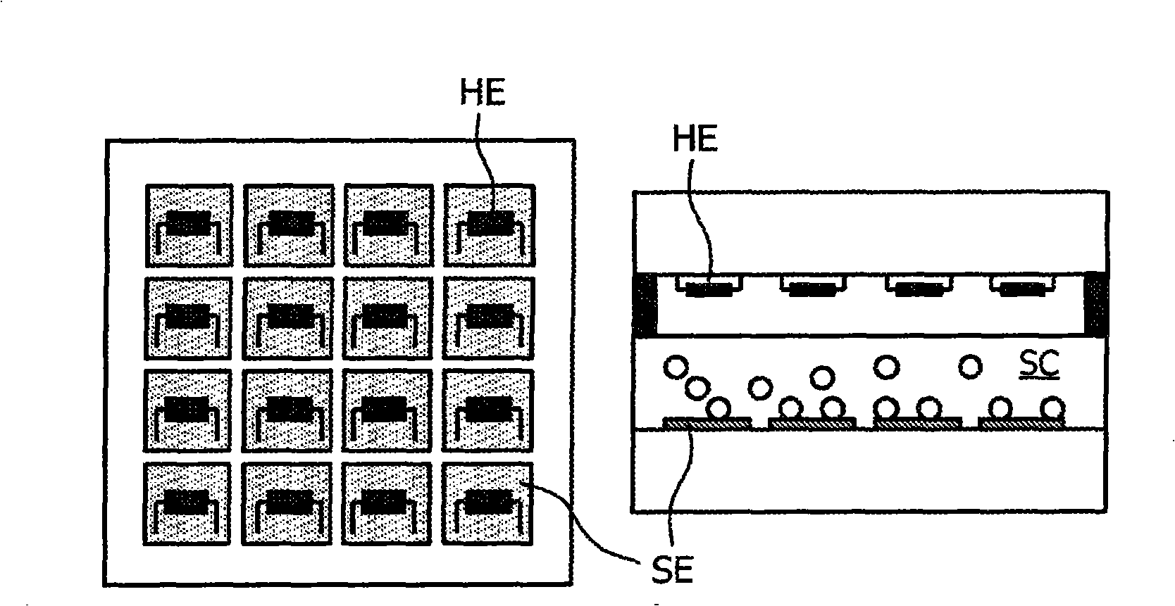
[0064] Biochips for (bio)chemical analysis, such as molecular diagnostics, will become an important tool for various medical, forensic and food applications. Typically, biochips include biosensors in which target molecules (e.g. proteins, DNA) are immobilized on biochemical surfaces with capture molecules and are subsequently detected using, for example, optical, magnetic or electrical detection schemes. The target molecule is detected. Examples of magnetic biochips are described in WO 2003 / 054566, WO2003 / 054523, WO 2005 / 010542 A2, WO 2005 / 010543 A1 and WO2005 / 038911 A1, which are hereby incorporated by reference into the present invention.

[0065] One way to improve the specificity of biosensors is to control the temperature, which is often used in hybridization assays to tune the tightness of binding of target biomolecules to functional surfaces, for example, the binding of a DNA strand to its complementary strand. A high degree of compactness is required when eg single po...


PUM


Abstract

The invention relates to different designs of a microelectronic sensor device comprising an array of heating elements (HE) and an array of sensor elements (SE) that are aligned with respect to each other adjacent to a sample chamber (SC). By applying appropriate currents to the heating elements (HE), the sample chamber can be heated according to a desired temperature profile.

Description

technical field [0001] The present invention relates to a microelectronic device having an array of heating elements for manipulating a sample in a sample chamber. Furthermore, the invention also relates to the use of such a microelectronic device, for example as a biosensor. Background technique [0002] Biosensors often require well-controlled temperatures to operate, for example because many biomolecules are only stable within a small temperature window (typically around 37°C), or biomolecules become unstable when the temperature exceeds this window. Inactive. Temperature adjustment is especially important for hybridization analysis. In these assays, temperature is often used to adjust how tightly a DNA strand binds to its complementary strand. For example, a high degree of compactness is required when single point mutations are of interest. The melting temperature range (ie, denaturation of DNA strands) for single point mutation hybridization can differ by only less ...

Claims


Application Information

Patent Timeline
Patent Type & Authority Applications(China)
IPC IPC(8): B01J19/00
Inventor M·T·约翰逊D·A·菲什M·W·G·蓬吉
Owner KONINKLIJKE PHILIPS ELECTRONICS NV
Why Eureka
Try Eureka