Touch sensor and operating method thereof

A sensor and touch technology, applied in the field of touch sensors, can solve the problems of not providing correction components and the failure of touch sensors.

Inactive Publication Date: 2009-04-08
ATLAB INC
View PDF0 Cites 5 Cited by
  • Summary
  • Abstract
  • Description
  • Claims
  • Application Information

AI Technical Summary

Problems solved by technology

[0008] However, although the impedance of the circuit device included in each of the first and second signal generators 21 and 22 changes according to the operating conditions, the conventional touch sensor does not provide a correction element.
As a result, the operating characteristics of the touch sensor may vary depending on the operating conditions, and worse, malfunctions may occur in the touch sensor

Method used


Image

  • Touch sensor and operating method thereof
  • Touch sensor and operating method thereof
  • Touch sensor and operating method thereof

Examples


Embodiment Construction

[0063] Hereinafter, exemplary embodiments of the present invention will be described in detail. However, the present invention is not limited to the exemplary embodiments disclosed below, but may be implemented in various types. Accordingly, the present exemplary embodiments are provided for complete disclosure of the present invention and to fully convey the scope of the present invention to those generally skilled in the art.

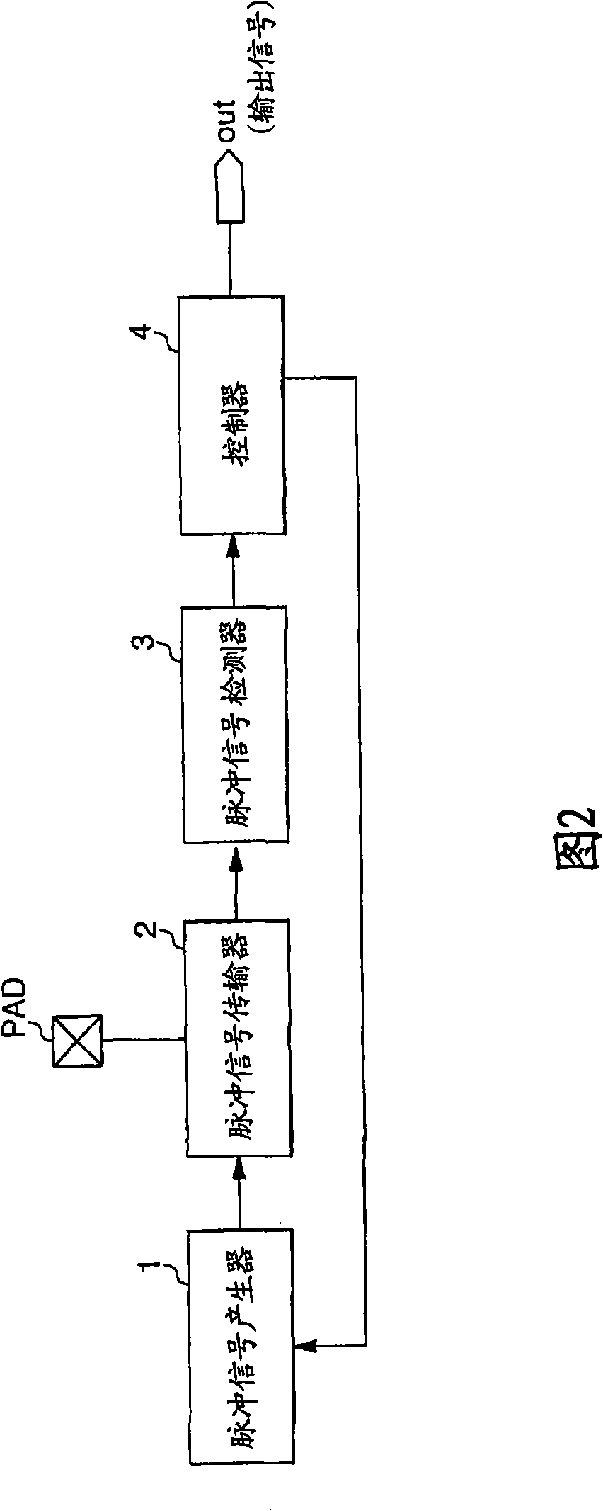
[0064] FIG. 2 is a block diagram of a touch sensor according to an exemplary embodiment of the present invention.

[0065] Referring to FIG. 2 , the touch sensor may include a pulse signal generator 1 , a pulse signal transmitter 2 , a pulse signal detector 3 and a controller 4 .

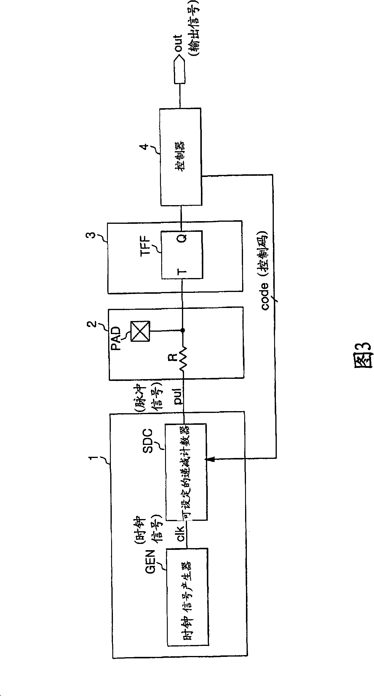
[0066] Specifically, the pulse signal generator 1 receives the code value of the control code "code" from the controller 4, sets the pulse width of the pulse signal "pul" according to the code value of the control code "code", and generates a pulse with the setting The wi...


PUM


Abstract

Provided are a touch sensor and a method of operating the same. The touch sensor includes: a pulse signal generator for generating a pulse signal of which pulse width is calibrated in response to a control code; a pulse signal transmitter for transmitting the pulse signal when a touch object is out of contact with a touch pad and stopping transmitting the pulse signal when the touch object is in contact with the touch pad; a pulse signal detector for detecting the pulse signal transmitted through the pulse signal transmitter; and a controller recognizing a non-contact state and adjusting the control code to calibrate the pulse width of the pulse signal when the pulse signal detector detects the pulse signal. In the above-described configuration, the contact of the touch object with the touch pad can be sensed more precisely, and the occurrence of a malfunction in the touch sensor due to changed operating conditions can be prevented. As a result, the operating reliability of the touch sensor can be enhanced.

Description

technical field [0001] The present invention relates to a touch sensor, and more specifically, to a touch sensor capable of sensing whether the touch object is in contact with the touch sensor by using the electrostatic capacitance of the touch object. Background technique [0002] Korean Patent Application No. 2005-23382 discloses a touch sensor as shown in FIG. 1 , which senses a touch by changing the delay time difference between a touch signal and a reference signal by using the electrostatic capacitance of a touch object. Whether the object is in contact with the touch sensor. [0003] 1, the touch sensor includes a reference signal generator (reference signal generator) 10, a first signal generator 21, a second signal generator 22, a touch signal generator (touch signal generator) 30 and a low-pass filter ( low pass filter, LPF) 40. Specifically, the reference signal generator 10 generates the reference signal ref_sig. The first signal generator 21 including the res...

Claims


Application Information

Patent Timeline
Patent Type & Authority Applications(China)
IPC IPC(8): G01R27/26
CPCG06F3/044G01R27/26
Inventor 文炳埈李芳远
Owner ATLAB INC
Why Eureka
Try Eureka