Pulse laser apparatus

A pulsed laser and excitation light technology, applied in lasers, laser parts, phonon exciters, etc., can solve problems such as difficulty in obtaining, weakening of Q-switching function, and inability to obtain laser characteristics.

Inactive Publication Date: 2010-10-20
HAMAMATSU PHOTONICS KK
View PDF6 Cites 3 Cited by
  • Summary
  • Abstract
  • Description
  • Claims
  • Application Information

AI Technical Summary

Problems solved by technology

[0004] However, shortening the length of the resonator will involve shortening the length of the laser medium or saturable absorber, resulting in an antinomy between it and the laser oscillation characteristics
In short, if the laser medium is shortened, it will be difficult to obtain sufficient absorption (excitation) for the population inversion (population inversion) necessary for laser oscillation, thereby reducing the energy of the output pulsed light.
In addition, if the saturable absorber is shortened, the function of the Q switch will be weakened, the pulse width will increase, and the output pulse energy will decrease, so that the desired laser characteristics cannot be obtained.

Method used


Image

  • Pulse laser apparatus
  • Pulse laser apparatus
  • Pulse laser apparatus

Examples


no. 1 Embodiment approach

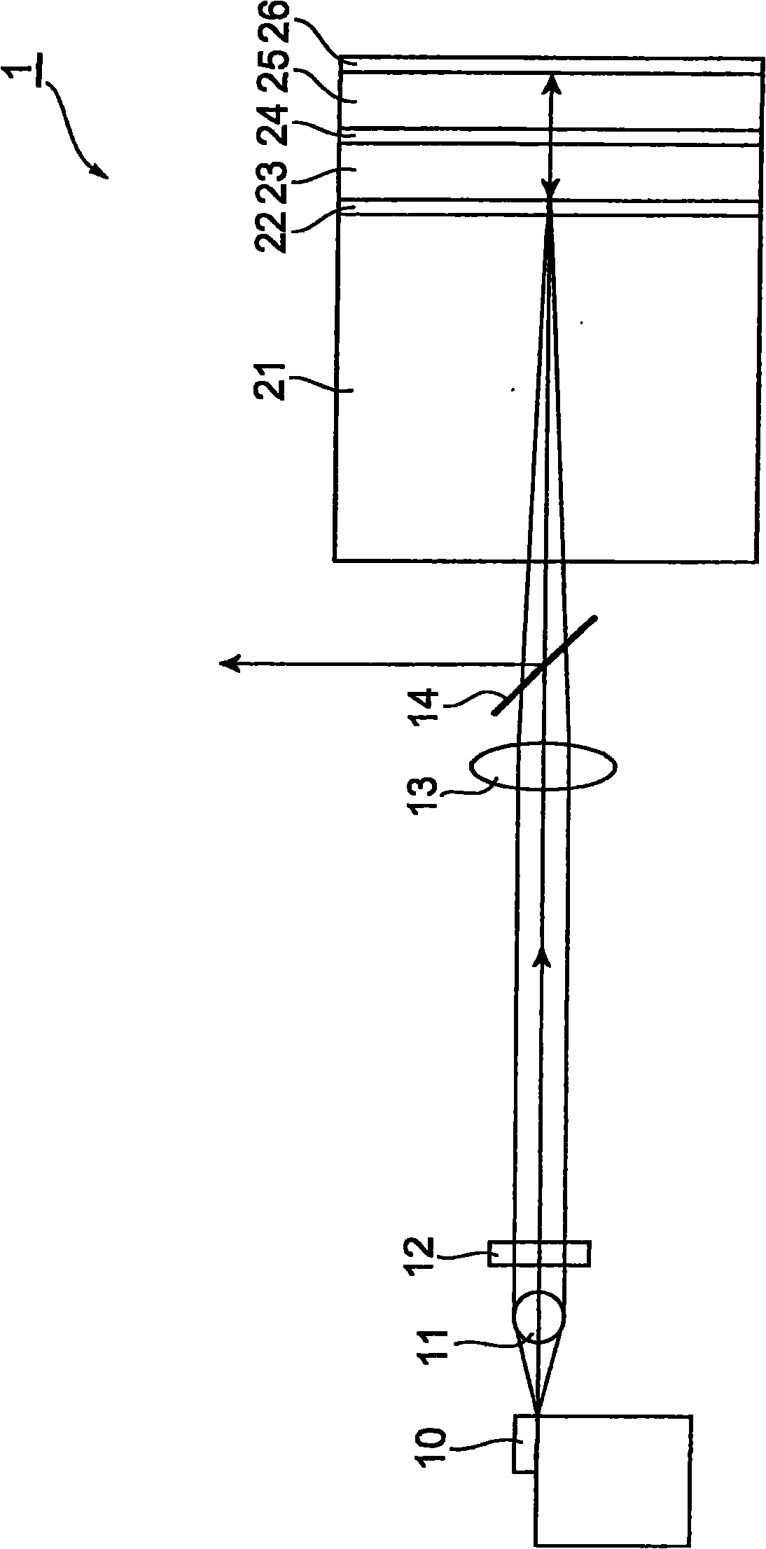
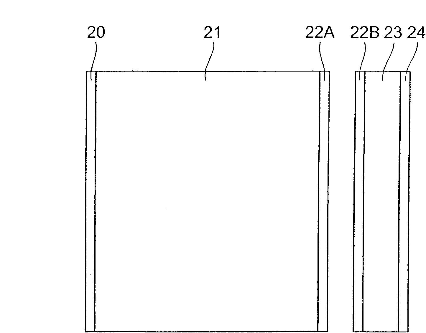
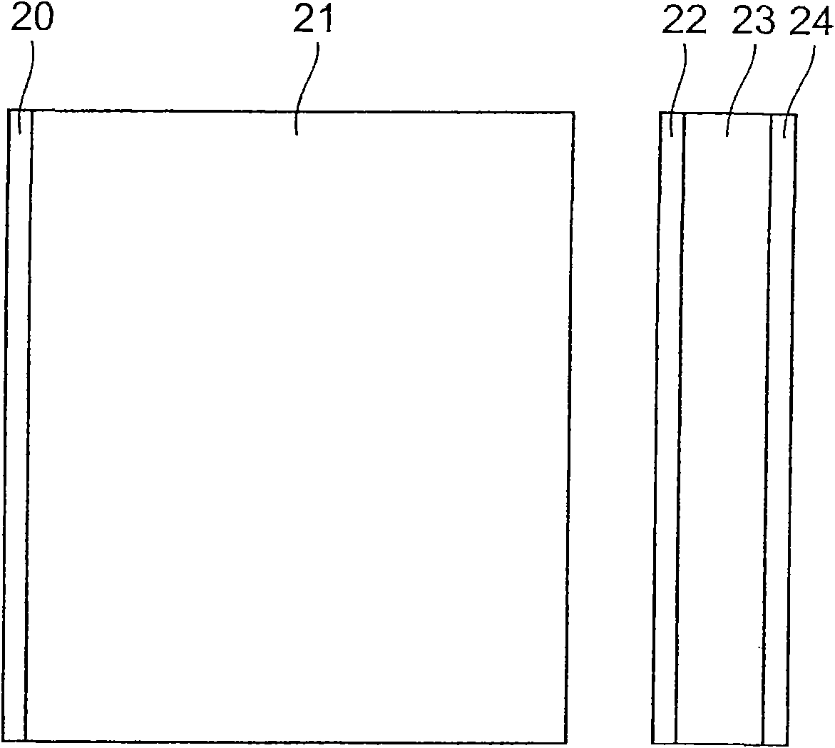
[0022] figure 1 It is a schematic diagram of the configuration of the pulsed laser light source 1 according to the first embodiment. The pulsed laser light source 1 shown in this figure includes an excitation light source 10, lenses 11 to 13, a dichroic mirror 14, an amplification medium 21, a first reflector 22, a laser medium 23, a third reflector 24, a saturable The absorber 25 and the second reflector 26 .

[0023] The amplifying medium 21 and the laser medium 23 each contain a photoactive material, are excited by being supplied with excitation light output from the excitation light source 10 , and emit light from the photoactive material. Preferably, the amplification medium 21 and the laser medium 23 are respectively crystals such as Nd:YAG or Yb:YAG. The thickness of the amplification medium 21 is, for example, 0.2 mm to 1.5 mm. The thickness of the laser medium 23 is, for example, 0.01 mm to 1.5 mm.

[0024] The saturable absorber 25, whose light absorptivity decre...

no. 2 Embodiment approach

[0055] Figure 5 It is a schematic diagram of the structure of the pulsed laser light source 2 concerning 2nd Embodiment. The pulsed laser light source 2 shown in this figure has an excitation light source 10 , lenses 11 to 13 , a dichroic mirror 14 , an amplification medium 21 , a first reflector 22 , a laser medium 23 , a saturable absorber 25 and a second reflector 26 .

[0056] and figure 1 Compared with the pulsed laser light source 1 according to the first embodiment shown, the Figure 5 The pulsed laser light source 2 according to the second embodiment shown is different in that it does not include the third reflector 24 . That is, the laser medium 23 and the saturable absorber 25 are directly bonded. In addition, in the second embodiment, the reflector 26 reflects not only emission light but also excitation light with high reflectivity.

[0057] The pulsed laser light source 2 according to the second embodiment operates as follows. The excitation light output from...

no. 3 Embodiment approach

[0062] Image 6 It is a schematic diagram of the structure of the pulsed laser light source 3 which concerns on 3rd Embodiment. The pulsed laser light source 3 shown in this figure has an excitation light source 10, lenses 11 to 13, a dichroic mirror 14, a 1 / 4 wavelength plate 15, an amplification medium 21, a first reflection part 22, a laser medium 23, and a saturable absorber 25. , the second reflection part 26 and the thermal diffusion parts 27-29.

[0063] and Figure 5 Compared with the structure of the pulsed laser light source 2 according to the second embodiment shown, the Image 6 The pulsed laser light source 3 according to the third embodiment shown is different in that it further includes a 1 / 4 wavelength plate 15 and thermal diffusion parts 27 to 29 .

[0064] The thermal diffusion parts 27 to 29 diffuse heat generated by light absorption in the laser medium 21 or the saturable absorber 23 . The thermal diffusion parts 27 to 29 are crystals not containing a pho...


PUM


Abstract

The invention relates to a pulse laser apparatus. A pulse laser light source 1 is provided with an excitation light source 10, lenses 11 through 13, a dichroic mirror 14, an amplifier medium 21, a first reflection portion 22, a laser medium 23, a third reflection portion 24, a saturable absorber 25 and a second reflection portion 26. The reflection portion 22 and the reflection portion 26 compose a laser resonator having the laser medium 23, the reflection portion 24 and the saturable absorber 25 on a resonance path. Further, the amplifier medium 21, the reflection portion 22, the laser medium 23, the reflection portion 24, the saturable absorber 25 and the reflection portion 26 are disposed in order and are integrated with each other. Therefore, the pulse laser light source 1 is able to output pulse laser light of high energy with a short pulse width.

Description

technical field [0001] The invention relates to a pulsed laser device. Background technique [0002] As a conventional pulsed laser light source, for example, light sources described in JP-A-9-508755, JP-A-11-261136, and JP-A-2006-73962 are known. These pulsed laser light sources are constituted by: having on the resonant optical path of the laser resonator, a laser medium which generates emission light by being supplied with excitation light; The rate decreases due to the saturation of light absorption. [0003] In the pulsed laser light source having the laser resonator configured as described above, the pulse width of the outputted pulsed laser light is generally 500 ps to several ns. The pulse width is determined by the structure of the laser resonator, and the length of the resonator is an important parameter for determining the pulse width. When it is desired to shorten the pulse width, the length of the resonator must be reduced. [0004] However, shortening the l...

Claims


Application Information

Patent Timeline
Patent Type & Authority Applications(China)
IPC IPC(8): H01S3/11H01S3/081H01S3/091H01S3/042
CPCH01S3/2308H01S3/09415H01S3/1618H01S3/1611H01S3/1118H01S3/0604H01S3/1643H01S3/0627H01S3/10092
Inventor 大桥弘之高新筱田和宪冈本博斋藤正之
Owner HAMAMATSU PHOTONICS KK
Why Eureka
Try Eureka