Piezoelectric ultrasonic wave guide probe for steel rail bottom flaw detection and flaw detection method thereof

A piezoelectric ultrasonic and ultrasonic guided wave technology, which is used in material analysis using sonic/ultrasonic/infrasonic waves, processing response signals of detection, measurement devices, etc. Problems such as low modal recognition and inapplicability to production practice, to achieve the effects of high flaw detection efficiency, easy promotion and low cost

Active Publication Date: 2018-05-29
DONGGUAN UNIV OF TECH
View PDF8 Cites 3 Cited by
  • Summary
  • Abstract
  • Description
  • Claims
  • Application Information

AI Technical Summary

Problems solved by technology

[0005] I Bartoli et al., J Zhang et al., Lu Chao et al. used the hammering method to conduct ultrasonic guided wave flaw detection of rails. However, in the guided wave signal obtained by the hammering method, the modal recognition degree of the guided wave is low, so the guided wave receiving transduction is required. The sensor is close to the damage point, which is often difficult to achieve in actual detection
In addition, the hammering method is not suitable for production practice
[0006] In recent years, non-contact ultrasonic guided wave flaw detection based on laser ultrasonic and air coupling has also made great progress, but there are still obvious defects in signal-to-noise ratio, accuracy, and generalizability.

Method used


Image

  • Piezoelectric ultrasonic wave guide probe for steel rail bottom flaw detection and flaw detection method thereof
  • Piezoelectric ultrasonic wave guide probe for steel rail bottom flaw detection and flaw detection method thereof
  • Piezoelectric ultrasonic wave guide probe for steel rail bottom flaw detection and flaw detection method thereof

Examples


Embodiment 1

[0059] This embodiment provides a piezoelectric ultrasonic guided wave probe, which can be used for rail bottom flaw detection, and makes up for the defect that traditional ultrasonic rail flaw detection technology has a large-area flaw detection blind area in the two sides of the rail bottom. , and the single detection distance is long, the typical single detection distance can reach ten meters to tens of meters, and the flaw detection efficiency is high.

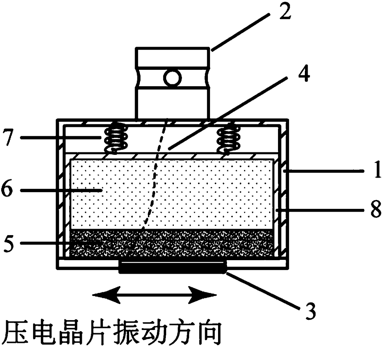
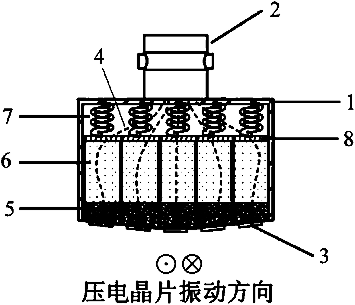
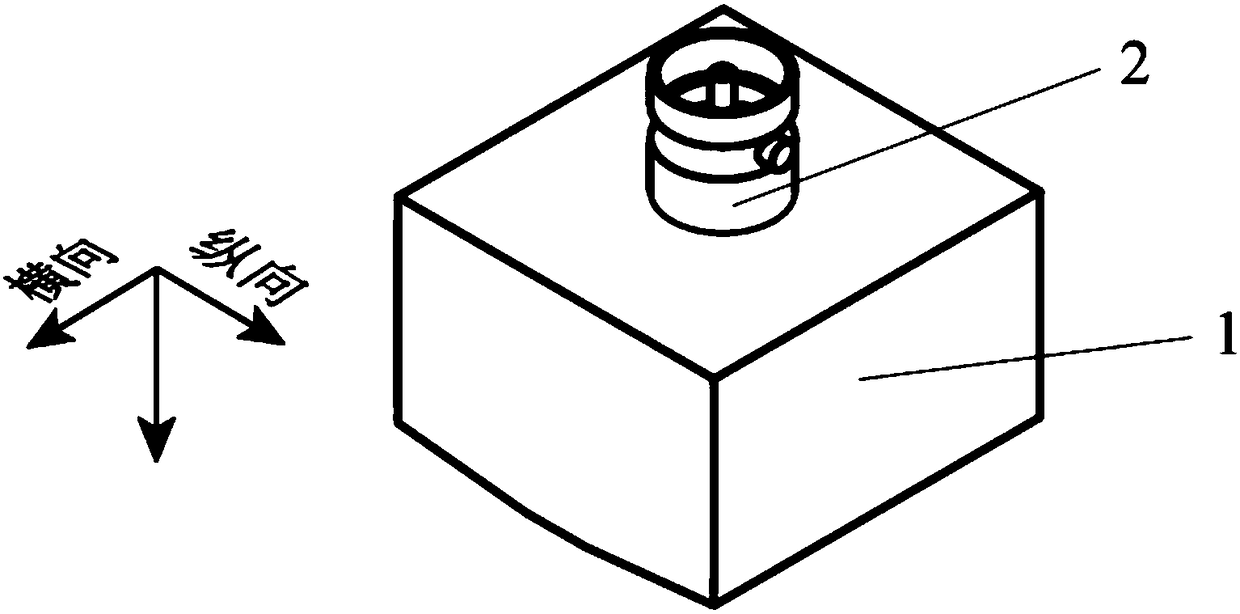
[0060] Such as Figure 1 ~ Figure 4 As shown, the piezoelectric ultrasonic guided wave probe of this embodiment includes an outer shell 1, five piezoelectric units and an interface 2, and each piezoelectric unit includes a piezoelectric wafer 3, a cable 4, a damping block 5, a suction Acoustic filler 6 , elastic element 7 and inner shell 8 .

[0061] Such as Figure 5 ~ Figure 8 As shown, the piezoelectric wafer 3 is selected as a piezoelectric ceramic sheet with a longitudinal vibration mode (LE mode), specifically a pi...

Embodiment 2

[0085] The main features of this embodiment are: the structure of the piezoelectric ultrasonic guided wave probe is the same as that of Embodiment 1, such as Figure 13 As shown, one side of the bottom of the rail is detected, but there are two piezoelectric ultrasonic guided wave probes 9, and the two piezoelectric ultrasonic guided wave probes 9 are placed on the upper surface of the side of the rail bottom of the rail 10, so that the piezoelectric The vibration direction of the wafer 3 is parallel to the length direction of the steel rail 10. During detection, a certain pressure is applied above the piezoelectric ultrasonic guided wave probe 9, so that the piezoelectric wafer 3 at the bottom of the piezoelectric ultrasonic guided wave probe 9 can be closely attached to the steel rail 10. The upper surface of this side of the bottom; the interfaces 2 of the two piezoelectric ultrasonic guided wave probes 9 are respectively connected to the excitation channel and the receiving c...

Embodiment 3

[0087] The main features of this embodiment are: the structure of the piezoelectric ultrasonic guided wave probe is the same as that of Embodiment 1, such as Figure 14 As shown, two piezoelectric ultrasonic guided wave probes 9 are placed on the upper surface of one side of the rail bottom of the rail 10 to detect one side of the rail bottom, but the external equipment includes an external excitation device 12 and an external receiving device 13, namely The excitation and reception functions of the signal are realized by different external devices. The interfaces 2 of the two piezoelectric ultrasonic guided wave probes 9 are respectively connected to the external excitation device 12 and the external receiving device 13, and the piezoelectric ultrasonic wave connected to the external excitation device 12 Guided wave probe 9, the piezoelectric chip 3 realizes the excitation of the guided wave through the inverse piezoelectric effect during detection, and the piezoelectric ultra...


PUM


Abstract

The invention discloses a piezoelectric ultrasonic wave guide probe for steel rail bottom flaw detection and a flaw detection method thereof. The probe comprises an outer layer casing, a plurality ofpiezoelectric units and at least one interface, wherein each piezoelectric unit comprises a piezoelectric wafer, a cable wire, a damping block, a sound absorption filling material, an elastic elementand an inner layer casing; the piezoelectric wafer is a piezoelectric ceramic piece with the length direction vibration mode and is arranged at the bottom of the outer layer casing; the vibration direction is parallel to the horizontal surface; one side, parallel to the vibration direction and near the inside, of the piezoelectric wafer is tightly attached to the damping block; the damping block is arranged in the inner layer casing; the sound absorption filling material is filled between the damping block and the inner layer casing; the elastic element is arranged between the inner layer casing and the outer layer casing; the connector is arranged on the top of the outer layer casing and is connected with the piezoelectric wafer through the cable wire. The piezoelectric wafer with the length direction vibration mode is used; the sensitivity is high; the single-time detection distance is long; the signal-to-noise ratio is high; the small damage can be inspected out; meanwhile, the costis low; the popularization is convenient.

Description

technical field [0001] The invention relates to a flaw detection device and a flaw detection method thereof, in particular to a piezoelectric ultrasonic guided wave probe and a flaw detection method for rail bottom flaw detection, belonging to the technical field of nondestructive testing. Background technique [0002] Rail flaw detection is one of the key tasks to ensure the safe operation of trains. At present, ultrasonic technology is generally used for rail flaw detection. The ultrasonic probe transmits pulsed sound waves from the rail head tread to the rail and receives its reflected waves to detect damage. Ultrasonic flaw detection technology can only inspect a local area around the probe each time pulsed sound waves are emitted, and there are large flaw detection blind spots on both sides of the rail bottom. Although rail head damage is still the main factor causing rail breakage, the number of rail breakage events or accidents caused by rail bottom damage has also s...

Claims


Application Information

Patent Timeline
Patent Type & Authority Applications(China)
IPC IPC(8): G01N29/24G01N29/44
CPCG01N29/245G01N29/449G01N2291/0289G01N2291/0234G01N2291/2623
Inventor 林荣马宏伟温宇立
Owner DONGGUAN UNIV OF TECH
Why Eureka
Try Eureka