
Encoding device, pulse generation device, and communication system

A technology of an encoding device and a reproducing device, which is applied to pulse conversion, transmission systems, synchronization devices, etc., can solve the problems of inability to correctly identify received data, secondary readout of received data, and omission of received data, and achieve good encoding efficiency. , the effect of reducing data errors and simple synchronization

Inactive Publication Date: 2009-04-08
ISHIDA CO LTD
View PDF4 Cites 3 Cited by
  • Summary
  • Abstract
  • Description
  • Claims
  • Application Information

AI Technical Summary

Problems solved by technology

For example, as described above, in the case of reproducing the pulse signal to obtain binary data, if the timing of reproducing the pulse signal deviates, omission of received data and secondary reading of the received data will occur, and the received data cannot be correctly identified.

Method used


Image

  • Encoding device, pulse generation device, and communication system
  • Encoding device, pulse generation device, and communication system
  • Encoding device, pulse generation device, and communication system

Examples


Embodiment approach 1

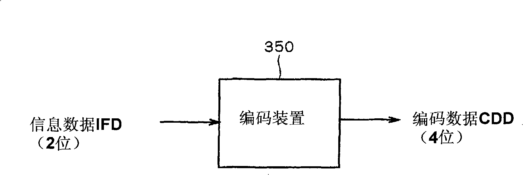
[0076] figure 1 This is a diagram showing an encoding device 350 according to Embodiment 1 of the present invention. like figure 1 As shown, the encoding device 350 according to the first embodiment converts the 2-bit information data IFD into the 4-bit encoded data CDD according to a predetermined encoding rule.

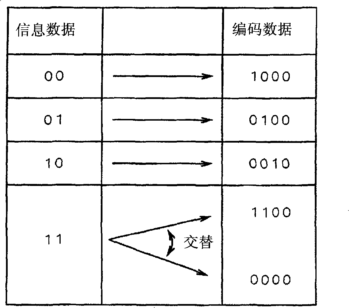
[0077] figure 2 This is a diagram showing an encoding rule used in the encoding device 350 . like figure 2 As shown, according to this encoding rule, the bit string "00" of the 2-bit information data IFD is converted into the bit string "1000" of 4 bits, the bit string "01" is converted into the bit string "0100", and the bit string "10" " is converted to the bit string "0010". Also, the bit string "11" of the information data IFD is alternately converted into the bit string "1100" and the bit string "0000". Specifically, the encoding device 350 converts the input bit string "11" into a bit string "1100", converts the input bit string "11" into a bit string ...

Embodiment approach 2

[0145] Figure 21 It is a figure which shows the structure of the communication system of Embodiment 2 of this invention. The communication system of the second embodiment is, for example, an optical communication system. like Figure 21 As shown, the communication system according to Embodiment 2 includes a transmitter 150 and a receiver 160 that receives an optical signal from the transmitter 150 .

[0146] The transmitting device 150 includes a data generating unit 151 that generates data to be transmitted to the receiving device 160, a data encoding unit 152 that encodes the data generated by the data generating unit 151 according to a predetermined encoding rule, a light-emitting unit 153 that outputs light, and a The light emission control unit 154 of the light emission unit 153 is controlled by the data encoded by the data encoding unit 152 .

[0147] The data generation unit 151 generates binary data and outputs the binary data to the data encoding unit 152 as infor...


PUM


Abstract

The present invention provides an encoding device, a pulse reproducing apparatus and a communication system. It is possible to provide an encoding technique having a preferable encoding efficiency and capable of being synchronized with encoded data. In order to achieve the object, an encoding device converts 2-bit information data into 4-bit encoded data according to a predetermined encoding rule. In the encoding rule used in the encoding device, among four types of bit strings which can be used by the information data, any one type of the bit strings is alternately converted into a 4-bit string in which each of continuous two bits has a values '1' and a 4-bit string in which all the bits have a value '0'. The other types of the bit strings are converted into 4-bit strings in which only one bit has a value '1' so that the bit strings after encoding are different from one another.

Description

technical field [0001] The present invention relates to a technique for encoding multi-bit information data according to a predetermined encoding rule, and a technique for reproducing, on the receiving side, a pulse signal generated on the transmitting side. Background technique [0002] Heretofore, various techniques have been proposed for encoding methods for transmitting data to a communication path. For example, Patent Documents 1 and 2 disclose an encoding method called a PPM (Pulse Position Modulation) method. In the PPM method, for example, 2-bit data representing "00", "01", "10" and "11" are converted into 4-bit data representing "1000", "0100", "0010" and "0001", respectively data. [0003] In addition, Patent Documents 3 and 4 disclose an encoding method called a CMI (Coded Mark Inversion) method. In the CMI method, 1-bit data representing "1" is alternately converted into 2-bit data representing "11" and "00", and 1-bit data representing "0" is converted into ...

Claims


Application Information

Patent Timeline
Patent Type & Authority Applications(China)
IPC IPC(8): H04L25/49H03M5/06H04L7/00
Inventor 水川繁光
Owner ISHIDA CO LTD
Learn More