Slug catching system

A technology of breaking plugs and swirl tubes, which is applied in the field of multiphase fluid transportation in oil and gas fields, can solve problems affecting the safety and normal operation of downstream equipment, equipment impact force and pressure fluctuations, etc., achieve good separation effects, reduce pressure fluctuations, reduce gas The effect of liquid entrainment

Inactive Publication Date: 2009-04-15
XIAN CHANGQING TECH ENG
View PDF0 Cites 7 Cited by
  • Summary
  • Abstract
  • Description
  • Claims
  • Application Information

AI Technical Summary

Problems solved by technology

[0002] In engineering, two-phase (or multi-phase) fluid pipelines are usually used to transport gas and liquid at the same time. Due to the difference in the flow rate and flow mode of each phase fluid during transportation, slug flow often occurs, which has a great impact on the equipment in the system Force and pressure fluctuations, affecting the safety and normal operation of downstream equipment

Method used


Image

  • Slug catching system
  • Slug catching system
  • Slug catching system

Examples


Embodiment Construction

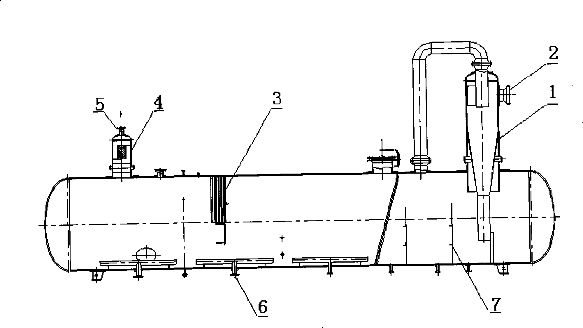
[0018] Example figure 1 As shown, the slug flow trapping device includes a cyclone device 1 , a gas rectifying device 3 , a vertical mist trapping and separating device 4 , and a buffer partition 7 . A swirl device 1 is installed vertically on the top of the right side of the tank, and the swirl device 1 is provided with a tangential inlet 2. There are two-stage buffer partitions 7 in the lower part of the swirl device 1, and the two-stage buffer partition 7 is close to the tank body to the left. An anti-vortex outlet 6 is provided at the bottom, a gas rectifying device 3 is provided near the top of the cylinder, a vertical mist trapping and separating device 4 is installed on the top of the left end of the cylinder, and the upper end of the vertical mist trapping and separating device 4 is a gas outlet 5.

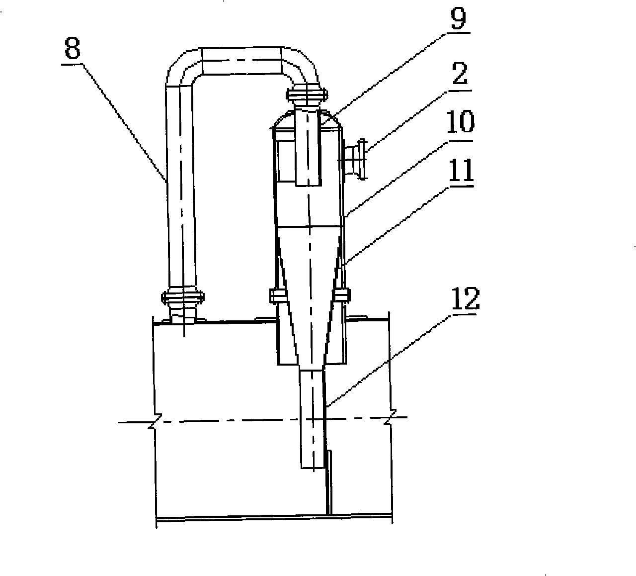
[0019] like figure 2 As shown, the cyclone device 1 includes a cyclone cylinder 10, a gas ascending section 9, a gas passing section 8, a swirl cone cylinder 11 and a li...


PUM


Abstract

The invention belongs to oil and gas equipment, and particularly relates to a plug flow scheme collecting system during production and establishment processes of oil and gas field. The collecting system is characterized in that the system comprises a tank body, a rotation flow device (1), a gas rectifier device (3), a vertical fog-collecting separation device (4) and a damping baffle (7); the top end at the right side of the tank body is vertically provided with the rotation flow device (1); the lower cylinder of the rotation flow device (1) is internally provided with a two-step damping baffle (7), the left side of which on the top position close to the middle position of the tank body is provided with the gas rectifier device (3); and the top of the left end of the tank body is provided with the vertical fog-collecting separation device (4) and the lower part thereof is provided with an anti-vortex outlet (6). Therefore, under the impact force and pressure fluctuation generated by the plug flow scheme, the plug flow scheme collecting system ensures the normal running of the instrument control system and the safety of the equipment body.

Description

technical field [0001] The invention belongs to oil and gas equipment, in particular to a plug-flow trapping system in oil and gas field production and construction projects, and is especially suitable for the field of multiphase fluid transportation in oil and gas fields. Background technique [0002] In engineering, two-phase (or multi-phase) fluid pipelines are usually used to transport gas and liquid at the same time. Due to the difference in the flow rate and flow mode of each phase fluid during transportation, slug flow often occurs, which has a great impact on the equipment in the system Force and pressure fluctuations affect the safety and normal operation of downstream equipment. Contents of the invention [0003] The purpose of the present invention is to provide a slug flow capture system to ensure the normal operation of the instrument control system and the safety of the equipment body under the impact force and pressure fluctuation generated by the slug flow....

Claims


Application Information

Patent Timeline
Patent Type & Authority Applications(China)
IPC IPC(8): F17D5/00F17D3/01
Inventor 郭亚红刘文喜郭信军蔺亚梅
Owner XIAN CHANGQING TECH ENG
Why Eureka
Try Eureka