LED light fitting

A technology of light-emitting diodes and lamps, which is applied to semiconductor devices, light sources, point light sources, etc.

Inactive Publication Date: 2009-04-15
FU ZHUN PRECISION IND SHENZHEN +1
View PDF0 Cites 13 Cited by
  • Summary
  • Abstract
  • Description
  • Claims
  • Application Information

AI Technical Summary

Problems solved by technology

[0002] Light Emitting Diode (LED) lighting devices are widely used in communication, lighting, transportation, outdoor billboards and other fields due to their advantages of energy saving and environmental protection. However, high brightness and high power LEDs will As a result, its luminous efficiency is significantly reduced, and even the components are damaged. Especially in order to increase the brightness and power of lighting, many light-emitting diodes are often arranged in a concentrated manner, which makes heat dissipation a big problem.
At present, the usual practice in the industry is to install heat dissipation fins under the LED lamps to dissipate heat. The heat dissipation fins conduct the concentrated heat to various places, and then dissipate the heat through natural convection. However, only relying on natural convection to dissipate heat The hot air in the fins dissipates slowly, and the hot air tends to accumulate around the LEDs, resulting in low heat dissipation efficiency
If the external electric fan provides forced convection, additional power consumption will be required, which is contrary to the concept of environmental protection and energy saving advocated by light-emitting diodes

Method used


Image

  • LED light fitting
  • LED light fitting
  • LED light fitting

Examples


Embodiment Construction

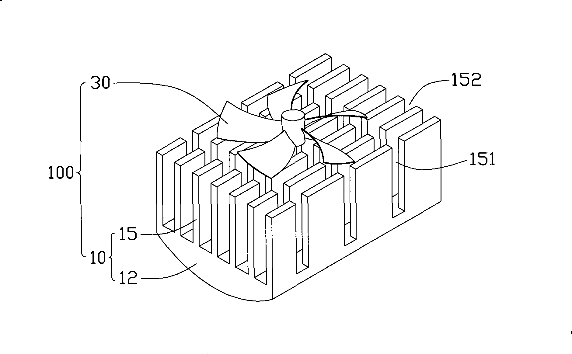
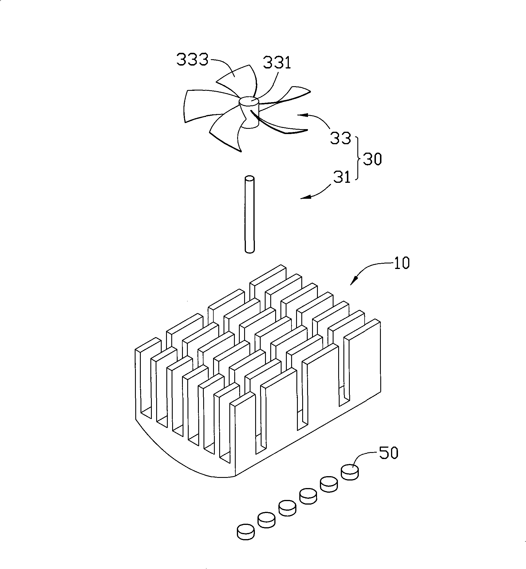
[0011] see figure 1 and figure 2 , is a heat dissipation device 100 according to an embodiment of the present invention. The heat dissipation device 100 includes a heat sink 10 and a temperature difference fan 30 arranged above the heat sink 10. The heat dissipation device 100 is used for heat dissipation in an LED lamp.

[0012] The heat sink 10 includes a base plate 12 and a plurality of heat dissipation fins 15 integrally extending upward from the top surface of the base plate 12 , and gaps 151 , 152 are spaced between the heat dissipation fins 15 horizontally and vertically. A plurality of LED modules 50 are mounted on the bottom of the substrate 12 . These LED modules 50 will generate a lot of heat during operation, and the heat will be conducted to the substrate 12 and the cooling fins 15 through contact with the substrate 12 .

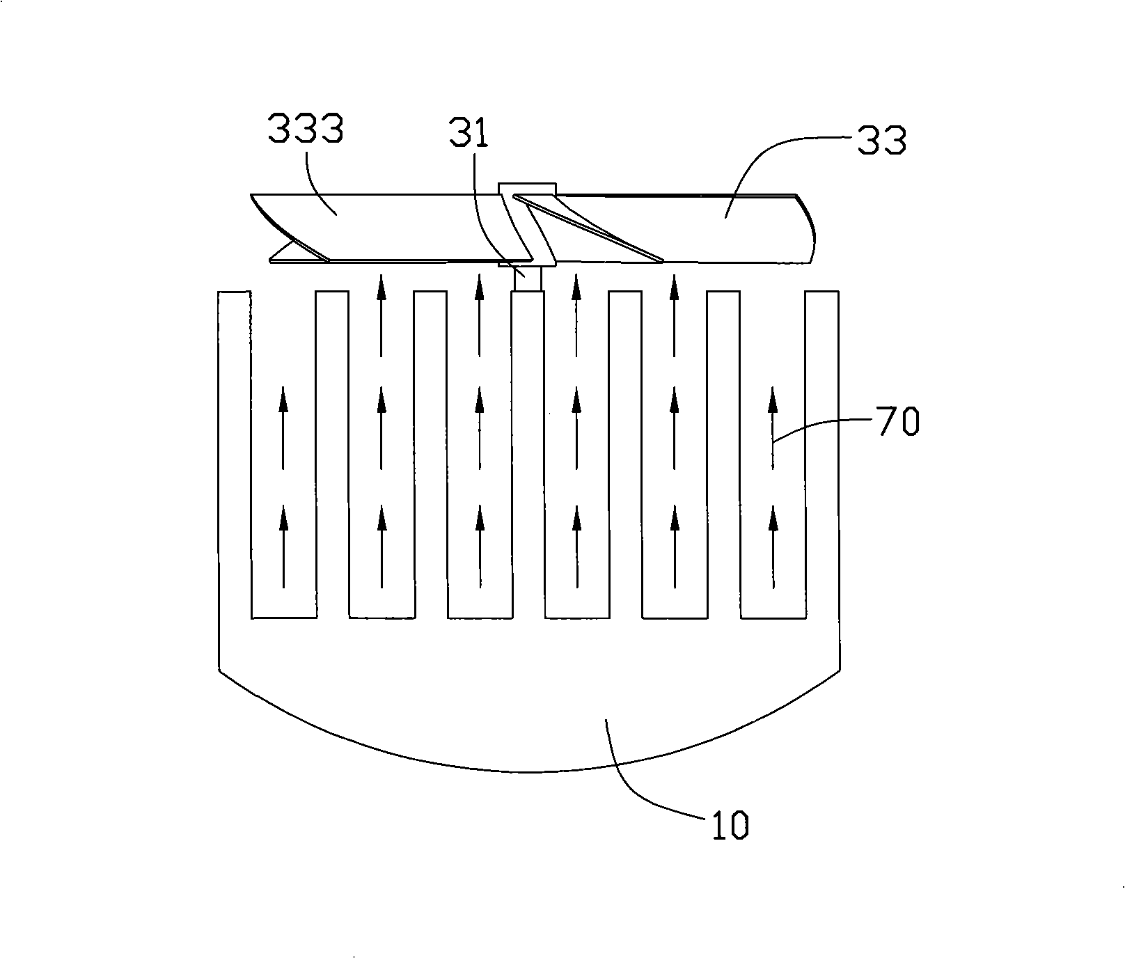
[0013] The temperature difference fan 30 includes a support column 31 and an impeller 33 rotatably mounted on the support column 31. The impe...


PUM


Abstract

The invention provides an LED lamp, comprising a plurality of LEDs and a heat dissipation device; wherein, the heat dissipation device comprises a radiator and a temperature difference fan which comprises an impeller; the heat dissipation device is vertically arranged in the LED lamp so as to lead the LED and the radiator to be arranged below the temperature difference fan; natural convection formed between the LED, the radiator and the temperature difference fan owning to the temperature difference drives the impeller of the temperature difference fan to rotate; the impeller of the temperature difference fan rotates under the collision of the hot airflow and drives more hot gas below to emanate towards the upper direction and surroundings; simultaneously, the air in horizontal direction and other directions of the vane of the fan generates strong disturbance under the fanning of the fan vane, the disturbed airflow is emanated towards the surroundings, thus being beneficial for the air exchange around the temperature difference fan, improving the convection condition of the air surrounding the heat dissipation device and improving the heat dissipation efficiency further. Simultaneously, the temperature difference fan needs not to be driven by power, thus meeting the concept of environmental protection and energy saving.

Description

technical field [0001] The invention relates to a light-emitting diode lamp, in particular to a light-emitting diode lamp with a fan. Background technique [0002] Light Emitting Diode (LED) lighting devices are widely used in communication, lighting, transportation, outdoor billboards and other fields due to their advantages of energy saving and environmental protection. However, high brightness and high power LEDs will As a result, the luminous efficiency is significantly reduced, and even the components are damaged. Especially in order to increase the lighting brightness and power, many light-emitting diodes are often arranged in a concentrated manner, which makes heat dissipation a big problem. At present, the usual practice in the industry is to install heat dissipation fins under the LED lamps to dissipate heat. The heat dissipation fins conduct the concentrated heat to various places, and then dissipate the heat through natural convection. However, only relying on nat...

Claims


Application Information

Patent Timeline
Patent Type & Authority Applications(China)
IPC IPC(8): F21V29/02H01L23/467F21Y101/02
CPCF21V29/004F21V29/02F21V29/2243F21Y2101/02F21V29/76F21Y2115/10F21V29/67
Inventor 蓝海詹顺渊黄中元
Owner FU ZHUN PRECISION IND SHENZHEN
Why Eureka
Try Eureka