
Liquid crystal display apparatus and drive method thereof

A technology of liquid crystal display device and liquid crystal display panel, which is applied in static indicators, nonlinear optics, optics, etc., can solve the problems of screen flickering of display devices, and achieve the effect of improving screen flickering and avoiding leakage of electricity.

Active Publication Date: 2009-04-15
INNOCOM TECH (SHENZHEN) CO LTD +1
View PDF0 Cites 23 Cited by
  • Summary
  • Abstract
  • Description
  • Claims
  • Application Information

AI Technical Summary

Problems solved by technology

[0008] In order to solve the problem of screen flickering in liquid crystal display devices in the prior art, it is necessary to provide a liquid crystal display device that can improve the problem of screen flickering

Method used


Image

  • Liquid crystal display apparatus and drive method thereof
  • Liquid crystal display apparatus and drive method thereof
  • Liquid crystal display apparatus and drive method thereof

Examples


Embodiment Construction

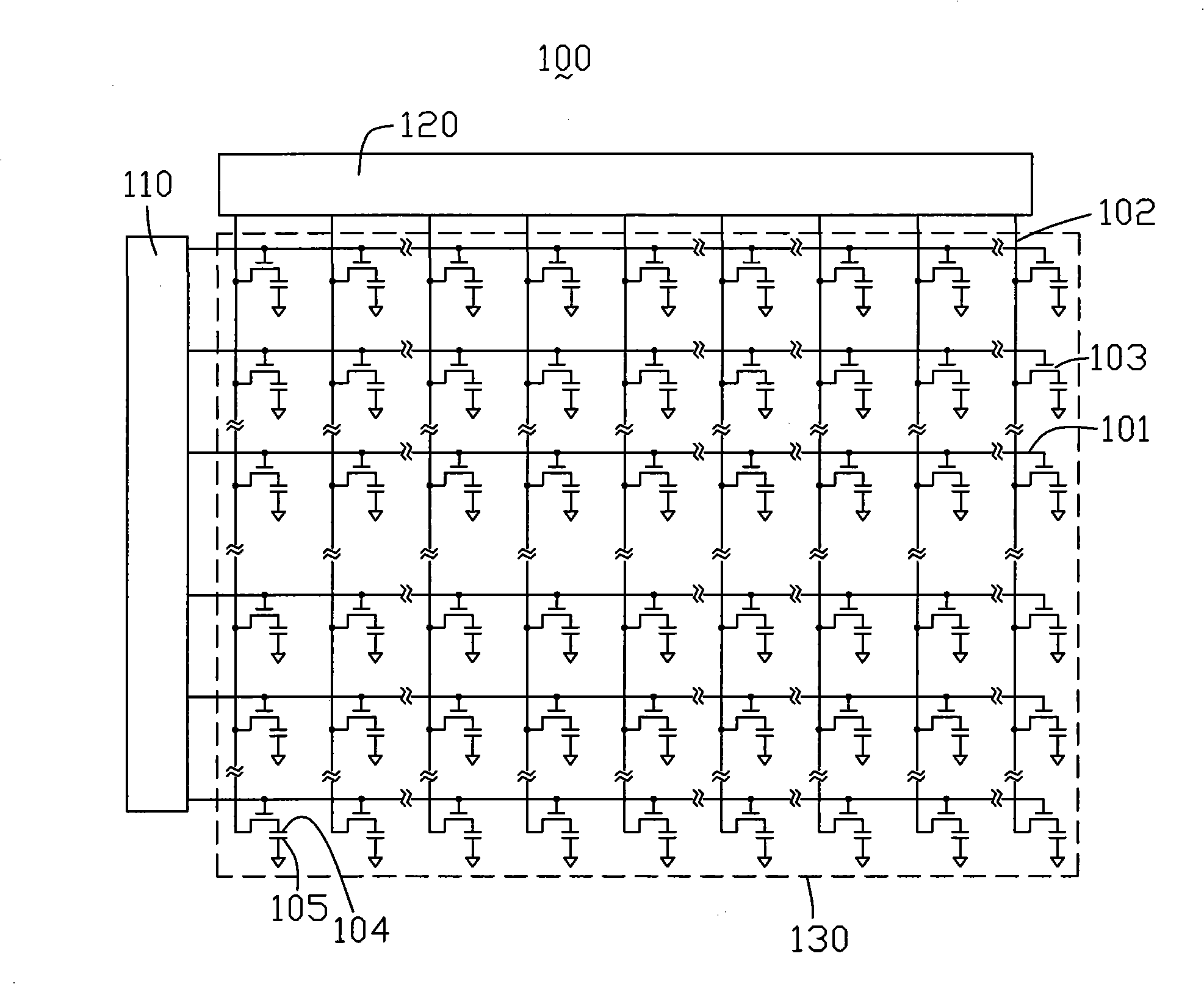
[0018] see Figure 4 , which is a schematic diagram of the circuit structure of the first embodiment of the liquid crystal display device of the present invention. The liquid crystal display device 400 includes a liquid crystal display panel 430 , a scan driving circuit 410 , a data driving circuit 420 and a delay compensation circuit 440 . The scanning driving circuit 410 is used to scan the liquid crystal display panel 430, the data driving circuit 420 is used to provide grayscale voltages to the liquid crystal display panel 430 when the liquid crystal display panel 430 is scanned, and the delay compensation circuit 440 is used to provide compensation The signal is sent to the liquid crystal display panel 430.

[0019] The liquid crystal display panel 430 includes a plurality of scan lines G parallel to each other. 1 ~G n (n is a natural number, n>1), multiple parallel to each other and the multiple scanning lines G 1 ~G n The data lines 402 that are vertically insulate...


PUM


Abstract

The invention relates to a liquid crystal displaying device which comprises a liquid crystal displaying panel, a scan driving circuit, a data driving circuit and a delay compensation circuit. The liquid crystal displaying panel comprises a plurality of scanning lines and a plurality of data wires which are insulate and orthogonal with the scanning lines. The delay compensation circuit comprises a plurality of capacitors which are corresponding to the scanning lines. The scan driving circuit is used for providing a plurality of scanning signals for the scanning lines. The data driving circuit is used for providing a gray scale voltage for the data wires when the scanning lines are scanned. When the scanning lines are scanned, the corresponding capacitor discharges and provides a compensation signal to the scanning line, and the corresponding capacitor of the next scanning line is charged while the corresponding capacitor of the previous scanning line is discharged to ground.

Description

technical field [0001] The invention relates to a liquid crystal display device and a driving method thereof. Background technique [0002] As liquid crystal display devices are more and more widely used in various fields, the liquid crystal display devices show a trend of developing toward larger sizes and higher resolutions. However, in a liquid crystal display device using a thin film transistor (Thin Film Transistor, TFT), the high-potential signal of the scanning line is obviously delayed due to the excessively long circuit wiring, thereby causing the problem of screen flickering. [0003] see figure 1 , which is a schematic diagram of a circuit structure of a prior art liquid crystal display device. The liquid crystal display device 100 includes a scan driving circuit 110 , a data driving circuit 120 and a liquid crystal display panel 130 . The scanning driving circuit 110 is used to scan the LCD panel 130 , and the data driving circuit 120 is used to provide graysc...

Claims


Application Information

Patent Timeline
Patent Type & Authority Applications(China)
IPC IPC(8): G02F1/133G02F1/1362G09G3/36
CPCG09G2320/0247G09G3/3677G09G2320/0223
Inventor 孟锴
Owner INNOCOM TECH (SHENZHEN) CO LTD
Learn More