Method for eliminating serial interference in multi-input multi-output system

A serial interference elimination and multi-output technology, applied in diversity/multi-antenna systems, space transmit diversity, prevention/detection of errors through diversity reception, etc., can solve the increased computational complexity of VBLAST signal detection and the complexity of matrix inverse operations Advanced problems, to achieve the effect of simplifying the computational complexity

Inactive Publication Date: 2009-04-15
TD TECH COMM TECH LTD
View PDF0 Cites 20 Cited by
  • Summary
  • Abstract
  • Description
  • Claims
  • Application Information

AI Technical Summary

Problems solved by technology

In the process of determining the next detected transmission signal each time, matrix inversion or pseudo-inversion operation is required, and the complexity of matrix inversion operation is very high, and, with the increase of the number of transmission antennas, the

Method used


Image

  • Method for eliminating serial interference in multi-input multi-output system
  • Method for eliminating serial interference in multi-input multi-output system
  • Method for eliminating serial interference in multi-input multi-output system

Examples


Embodiment 1

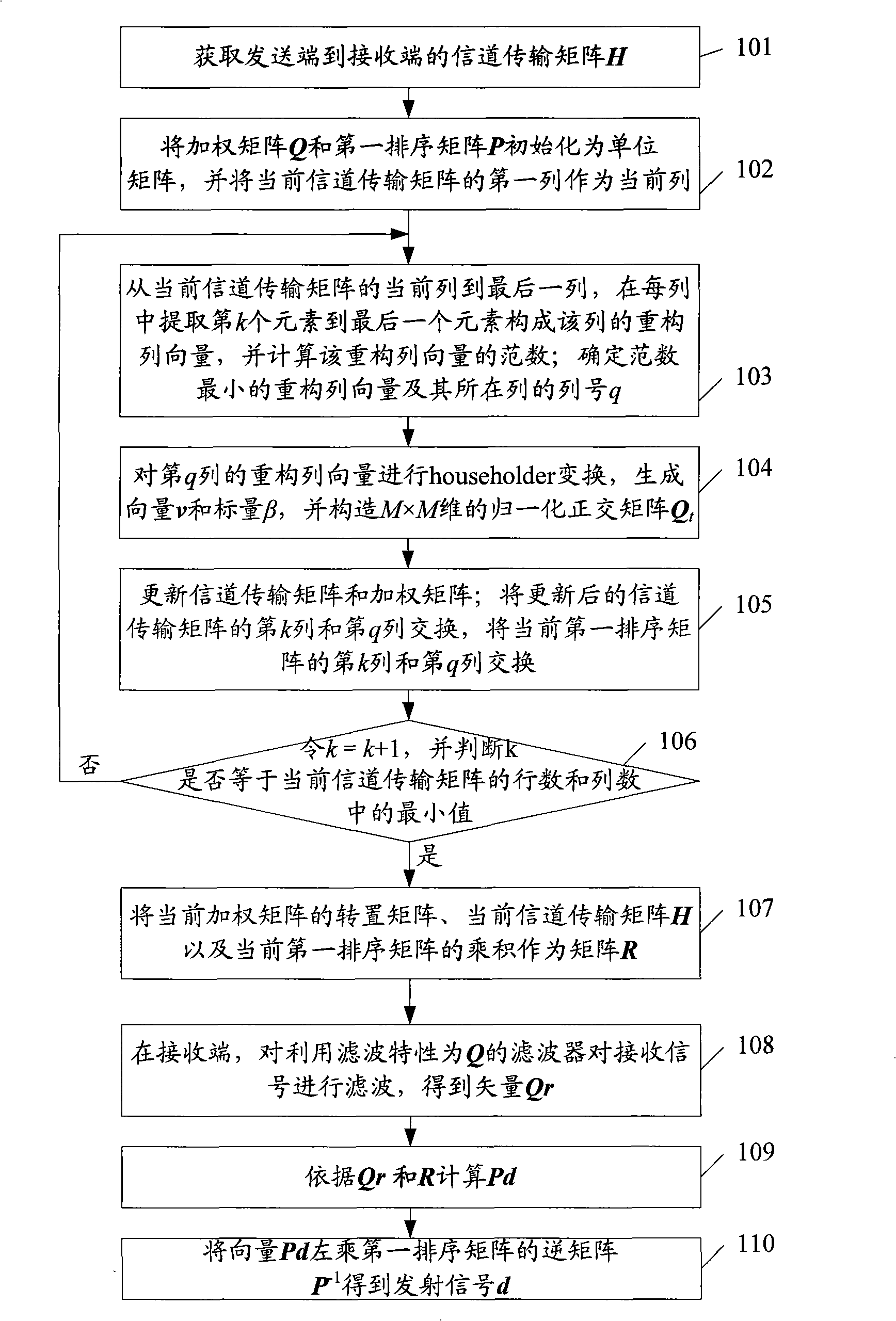
[0045] In this embodiment, the upper triangular matrix is ​​obtained through a simple sorting QR decomposition process. in N t root transmitting antenna, N r In a MIMO system with a root receiving antenna, figure 1 It is a specific flow chart of serial interference cancellation in Embodiment 1 of the present invention. Such as figure 1 As shown, the method includes:

[0046] Step 101, obtain the channel transmission matrix H from the sending end to the receiving end.

[0047] In this embodiment, channel estimation is performed at the receiving end, so as to obtain the channel transmission matrix H from the sending end to the receiving end.

[0048] Next, QR decomposition is performed on the channel transmission matrix H through steps 102-106, wherein the dimension of the QR decomposition matrix is ​​assumed to be M×N. In this embodiment, M=N r , N=N t .

[0049] Step 102, use the channel transmission matrix H obtained in step 101 as the current channel transmission ma...

Embodiment 2

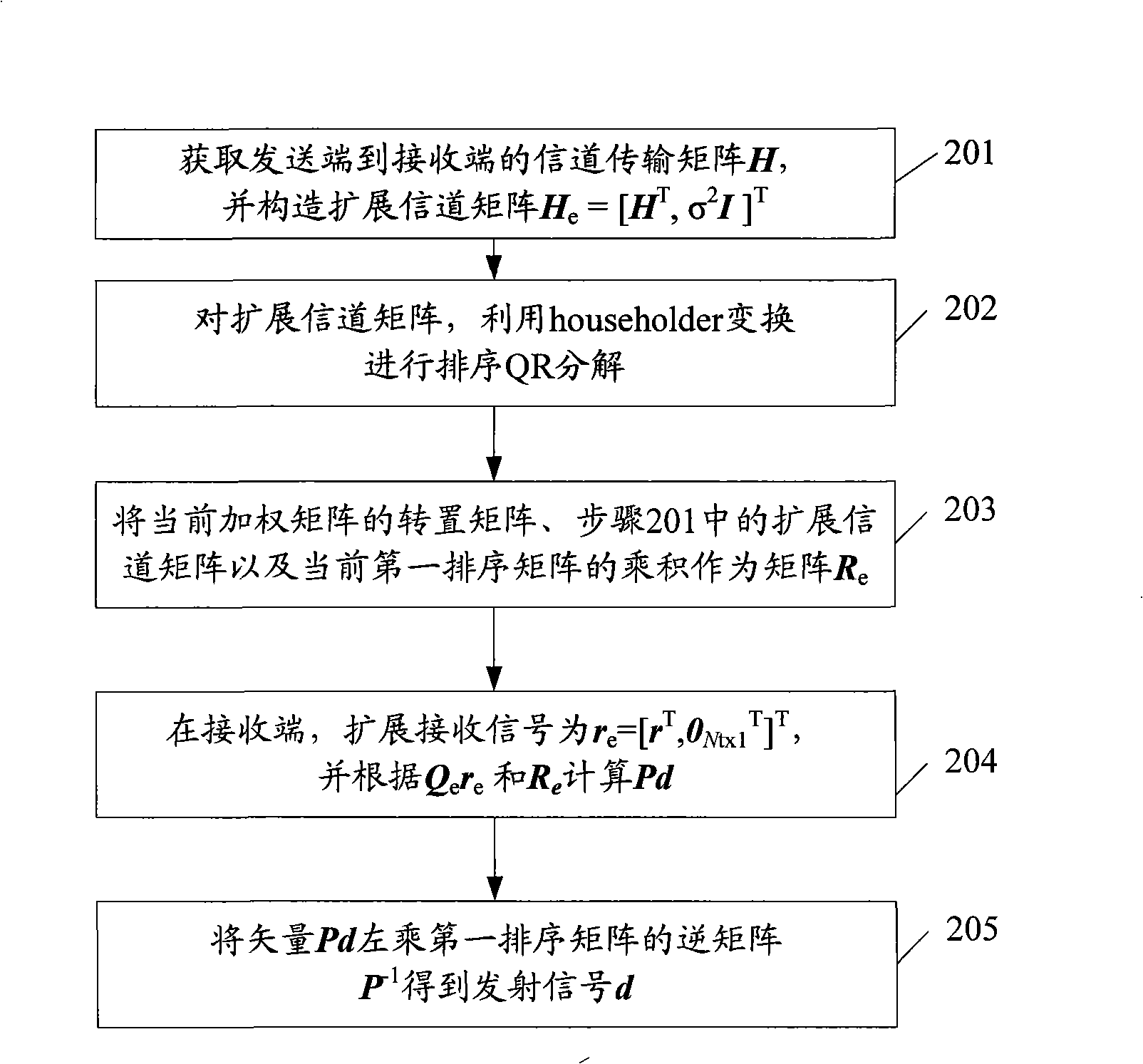
[0076] In this embodiment, the R matrix is ​​still obtained through simple sorting QR decomposition. specifically, figure 2 It is a specific flow chart of serial interference cancellation in Embodiment 2 of the present invention. Such as figure 2 As shown, the method includes:

[0077] Step 201, obtain the channel transmission matrix H from the sending end to the receiving end, and construct the extended channel matrix H e =[H T , σ 2 I] T , which is used as the current channel transmission matrix.

[0078] In this step, the receiving end obtains the channel transmission matrix H from the transmitting end to the receiving end through channel estimation, and then determines the current channel transmission matrix according to the channel transmission matrix H. The specific way to determine the current channel transmission matrix is: construct the extended channel matrix H according to the channel transmission matrix H e =[H T , σ 2 I] T , where σ 2 is the mean squ...

Embodiment 3

[0094] in N t root transmitting antenna, N r In a MIMO system with a root receiving antenna, Figure 4It is a specific flow chart of serial interference cancellation in Embodiment 3 of the present invention. Such as Figure 4 As shown, the method includes:

[0095] Step 401, acquire the channel transmission matrix H from the sending end to the receiving end.

[0096] In this embodiment, the sending end acquires the channel transfer matrix H from the sending end to the receiving end, the specific method may be: perform channel estimation at the receiving end to obtain the channel transfer matrix H from the sending end to the receiving end, and then the receiving end feeds back the estimation result to the sending end ; or in a system environment with the same uplink and downlink channel characteristics, the transmitting end performs channel estimation to obtain the channel transfer matrix from the receiving end to the sending end, and uses the channel estimation result as t...


PUM


Abstract

The invention discloses a successive interference cancellation method in a multiple input and multiple output system, comprising QR ordering and decomposition are carried out on a channel transmission matrix based on householder transformation to obtain an upper triangular matrix R, and according to the matrix R, precoding successive interference cancellation is executed on all the transmit signals, or the successive interference cancellation is executed on the received signal. As the matrix R is the upper triangular matrix, the successive interference cancellation can be sequentially executed on all the transmit signals by utilizing the characteristics of the upper triangular matrix, thus avoiding determining the successive detection sequence in a way using VBLAST for matrix inverse or pseudo-inverse, and further simplifying the computational complexity of the successive interference cancellation and improving the performance of signal detection.

Description

technical field [0001] The invention relates to signal detection technology, in particular to a multi-serial interference elimination method in a multiple-input multiple-output (MIMO) system. Background technique [0002] In the MIMO system, user signals are transmitted from multiple transmitting antennas after being multiplexed, and received by multiple receiving antennas at the receiving end. Vertical Bell Labs Layered Space-Time Architecture (VBLAST) based on Minimum Mean Square Error (MMSE) or Zero-Forcing (ZF) algorithm is a low-complexity serial detection method. [0003] Among them, the basic idea of ​​using the ZF algorithm for serial interference cancellation is: the receiving end detects each transmission signal in a certain order in the received signal, and after detecting each transmission signal, transmits the transmission signal to other transmission signals. The interference of the signal is eliminated, and then continue to detect the next transmission signal...

Claims


Application Information

Patent Timeline
IPC IPC(8): H04L1/06H04B7/04
Inventor 王大飞薛强拉盖施
Owner TD TECH COMM TECH LTD
Why Eureka
Try Eureka