Imaging system for automobile loop scene

An imaging system and automobile technology, which is applied in the field of automobile driving vision assistance system, can solve problems such as insufficient vision, and achieve the effect of improving safety

Inactive Publication Date: 2009-04-15
UNIV OF SHANGHAI FOR SCI & TECH
View PDF0 Cites 12 Cited by
  • Summary
  • Abstract
  • Description
  • Claims
  • Application Information

AI Technical Summary

Problems solved by technology

[0003] Aiming at the problem of the blind area caused by the insufficient field of view of the traditional automobile optical rearview mirror, the present invention proposes an automobile surround view imaging system

Method used


Image

  • Imaging system for automobile loop scene
  • Imaging system for automobile loop scene
  • Imaging system for automobile loop scene

Examples


Embodiment Construction

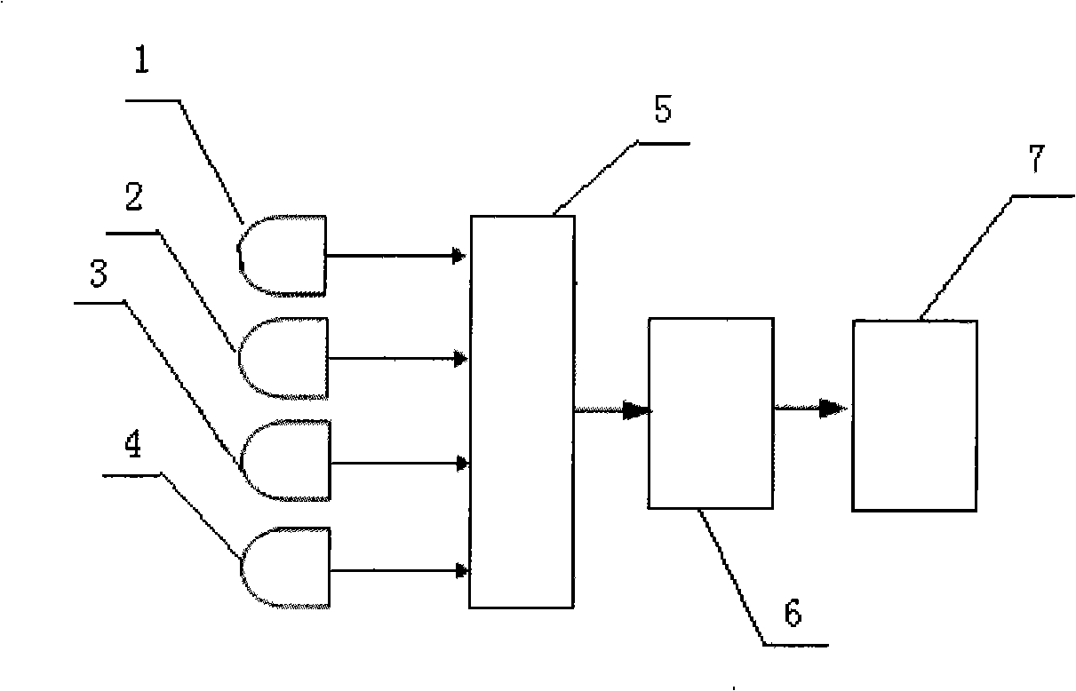
[0010] Such as figure 1 The principle block diagram of the automotive surround view imaging system shown in , the system includes a front camera 1, a left camera 2, a right camera 3, a rear camera 4, an image decoder 5, a DSP image module 6, and an LCD display 7. The four cameras 1, 2, 3, and 4 in the left and right directions collect the image information of the four directions of the car, send it to the image decoder 5 for signal decoding, and then enter the DSP image module 6 processing platform to restore the motion blur image first , image distortion compensation, viewpoint conversion processing, and then do image synthesis to realize the seamless connection of images, and finally input the final image to an LCD display screen 7 with a display module on the car console for display.

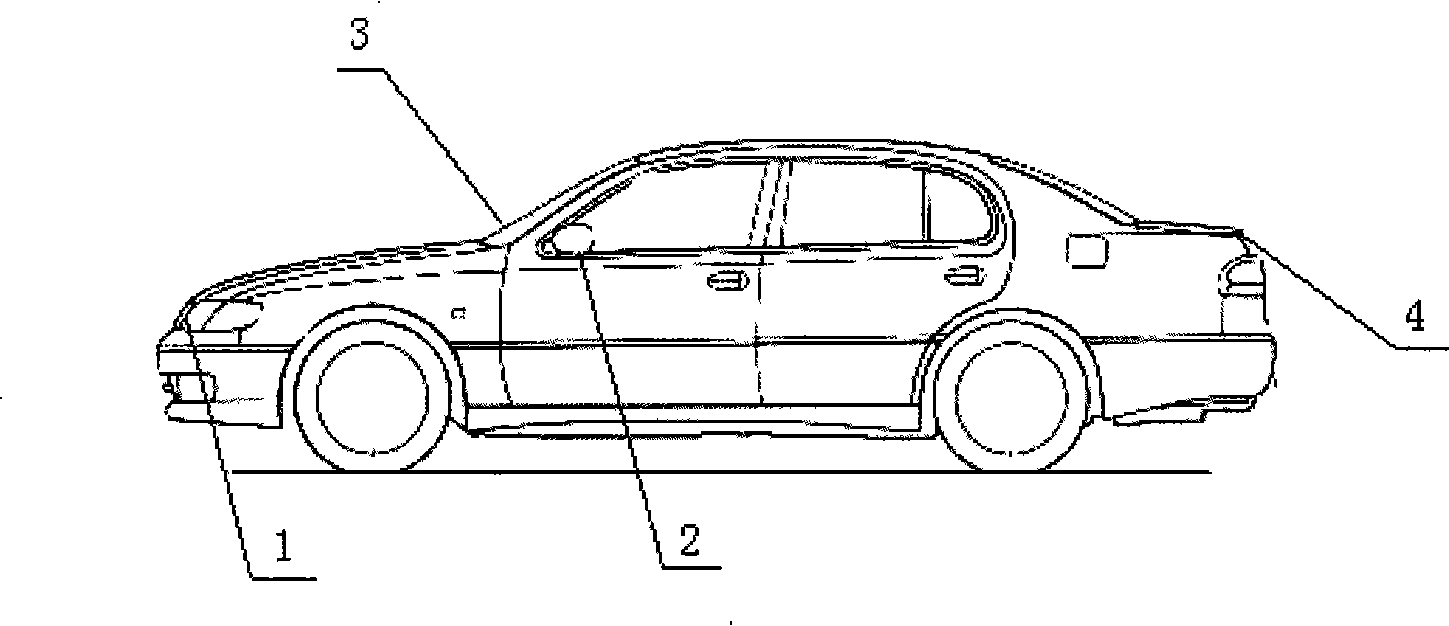
[0011] figure 2 In the installation diagram of the car surround view imaging system, the front camera 1 is installed at the front center of the car, the left camera 2 is installed at the bo...


PUM


Abstract

The invention relates to a vehicle environment imaging system, image information at four directions of a vehicle is collected by four camera heads which are positioned at front, back, left and right directions of a vehicle body, the image information is sent to a DSP image processing platform, the motion blurred image restoration, the image distortion compensation and the vision point conversion treatment are firstly carried out, then the image synthesis is carried out so as to realize the seamless connection of images, and a final image is finally input into an LCD display screen on a vehicle console for display, thereby solving the existing problem of having blind areas in the vehicle vision, ensuring the driving vehicle to achieve full perspectives and improving the safety of vehicles.

Description

technical field [0001] The invention relates to an automobile electronics industry, in particular to an automobile driving visual field assistance system. Background technique [0002] Ordinary cars are equipped with rearview mirrors for auxiliary vision, such as the left and right rearview mirrors on both sides of the body and the rearview mirror in the center of the car. These rearview mirrors are all flat mirrors or convex mirrors with a single curvature, or these rearview mirrors Changing to a multi-angle combined rearview mirror or a multi-curved large-view rearview mirror has played a role in improving driving safety to a certain extent, but there are generally problems with blind spots, such as spatial blind spots and time difference blind spots, which will inevitably cause Cause certain potential safety hazard to driving. Contents of the invention [0003] Aiming at the problem of the blind area caused by the insufficient field of view of the traditional automobil...

Claims


Application Information

Patent Timeline
Patent Type & Authority Applications(China)
IPC IPC(8): H04N5/262H04N7/18
Inventor 于莲芝王春阳冉焱张锐
Owner UNIV OF SHANGHAI FOR SCI & TECH
Why Eureka
Try Eureka