Optical objective module

An optical module and optical lens technology, applied in optics, optical components, installation, etc., can solve the problems of reduced image quality and reduced focusing accuracy.

Inactive Publication Date: 2009-04-15
PHYSIK INSTR PI
View PDF2 Cites 5 Cited by
  • Summary
  • Abstract
  • Description
  • Claims
  • Application Information

AI Technical Summary

Problems solved by technology

Moreover, the accuracy of focusing is significantly reduced
Imprecise focusing degrades image quality

Method used


Image

  • Optical objective module
  • Optical objective module
  • Optical objective module

Examples


Embodiment Construction

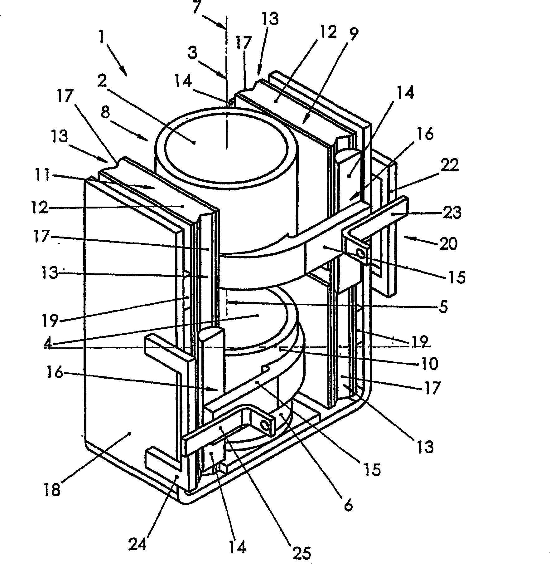
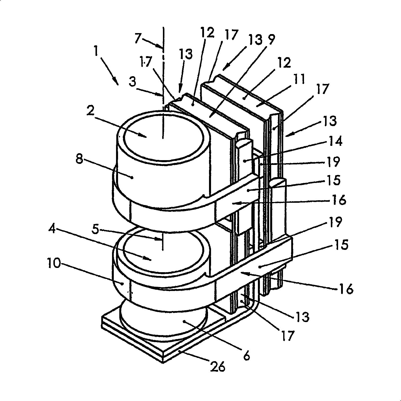
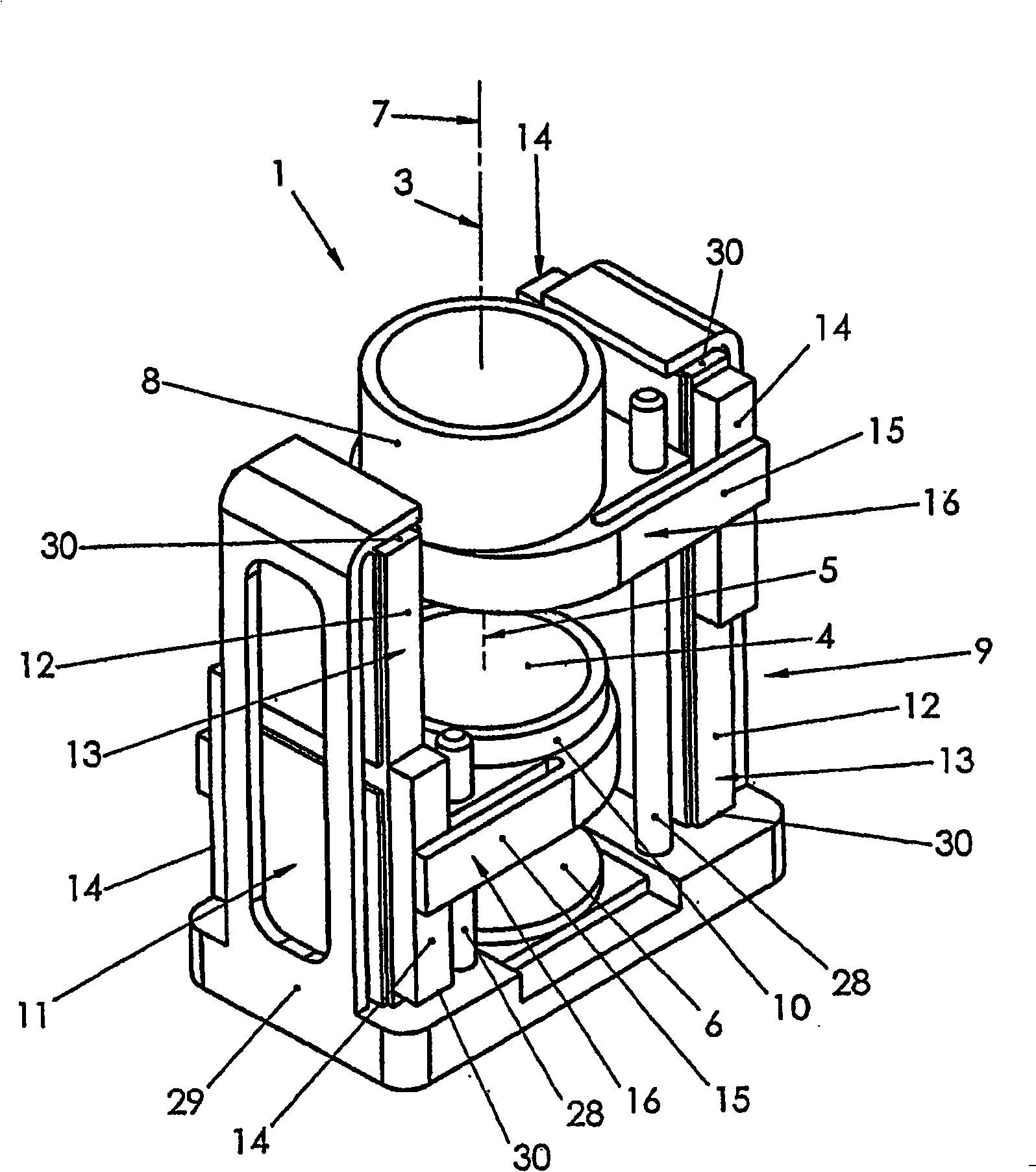
[0052] Optical Micromodule 1( figure 1 ) includes a zoom lens group 2 with an optical axis 3, a focusing optical lens group 4 with an optical axis 5, and a photoelectric imaging sensor 6. The two optical lens groups 2 , 4 are arranged such that their optical axes 3 and 5 coincide and together form the optical axis 7 of the optical module 1 .

[0053]The optical lens group 2 is mechanically connected to the first ultrasonic motor 9 by a mount 8 . The optical lens group 4 is mechanically connected to the second ultrasonic motor 11 by the carrier 10 .

[0054] The two ultrasonic motors 9 , 11 together form the drive of the optical module 1 .

[0055] The two ultrasonic motors 9 and 11 consist of a piezoelectric plate 12 with friction elements 14 which press against opposing side surfaces 13 . An elastic press-on element 15 pressing the friction element 14 against the side surface 13 forms part of the carrier 8 , 10 . The friction element 14 together with the pressing element ...


PUM


Abstract

The invention relates to an objective module comprising an optical zoom lens group (2) and a focusing optical lens group (4), the combined optical axes forming the optical axis (7) of the objective, and an electrical drive for the two lens groups. According to the invention, the electrical drive of the cited lens groups is embodied in the form of two linear ultrasonic motors (9, 11), each of the two ultrasonic motors consisting of a piezoelectric plate (12) comprising two friction elements (14) which are pressed against the opposing front sides and form the mobile elements of the ultrasonic motors together with the pressure elements (15). Each of the mobile elements is elastically connected to the corresponding lens group. The ultrasonic motors are arranged in such a way that the direction of displacement of the mobile elements is parallel to the optical axis of the optical module.

Description

technical field [0001] The invention relates to an optical objective module comprising an integrated ultrasonic drive according to the preamble of claim 1 . Such objective lens modules can be used in miniature high-precision cameras or video cameras. The invention can also be used in inexpensive miniature consumer electronic devices using the camera. Also included in laptop computers, tape recorders and mobile phones. Background technique [0002] Embodiments of an optical objective as a separate constructional unit are known, inside which are mounted an optical lens and as a drive a rotary ultrasonic motor which is arranged on the same axis as the lens and which moves the lens (cf. German patent DE 36 26 389A1). In these objectives, an ultrasonic traveling wave motor with a relatively large stator diameter is used. [0003] These ultrasonic motors have complex structures, their manufacture is labor-intensive and expensive, and they cannot be miniaturized. Therefore, su...

Claims


Application Information

Patent Timeline
Patent Type & Authority Applications(China)
IPC IPC(8): G02B7/10H01L41/09
CPCG02B7/102H02N2/026H02N2/065H02N2/062G02B7/023G02B7/08H02N2/008H02N2/002
Inventor 弗拉基米尔·维什涅夫斯基阿列克塞·维什涅夫斯基
Owner PHYSIK INSTR PI
Why Eureka
Try Eureka