Water-saving shower

A shower and one-cavity technology, which is applied to spray devices with movable outlets, spray devices, spray devices, etc., can solve the problems of reduced water outlet force, shower feeling that cannot be the same as ordinary showers, etc., and achieve the effect of small flow

Inactive Publication Date: 2009-04-22
周华松
View PDF0 Cites 8 Cited by
  • Summary
  • Abstract
  • Description
  • Claims
  • Application Information

AI Technical Summary

Problems solved by technology

However, although the flow rate of the water-saving sheet is reduced, the water outlet force is also reduced at the same time; for the method of reducing the water outlet, the

Method used


Image

  • Water-saving shower
  • Water-saving shower
  • Water-saving shower

Examples


Embodiment Construction

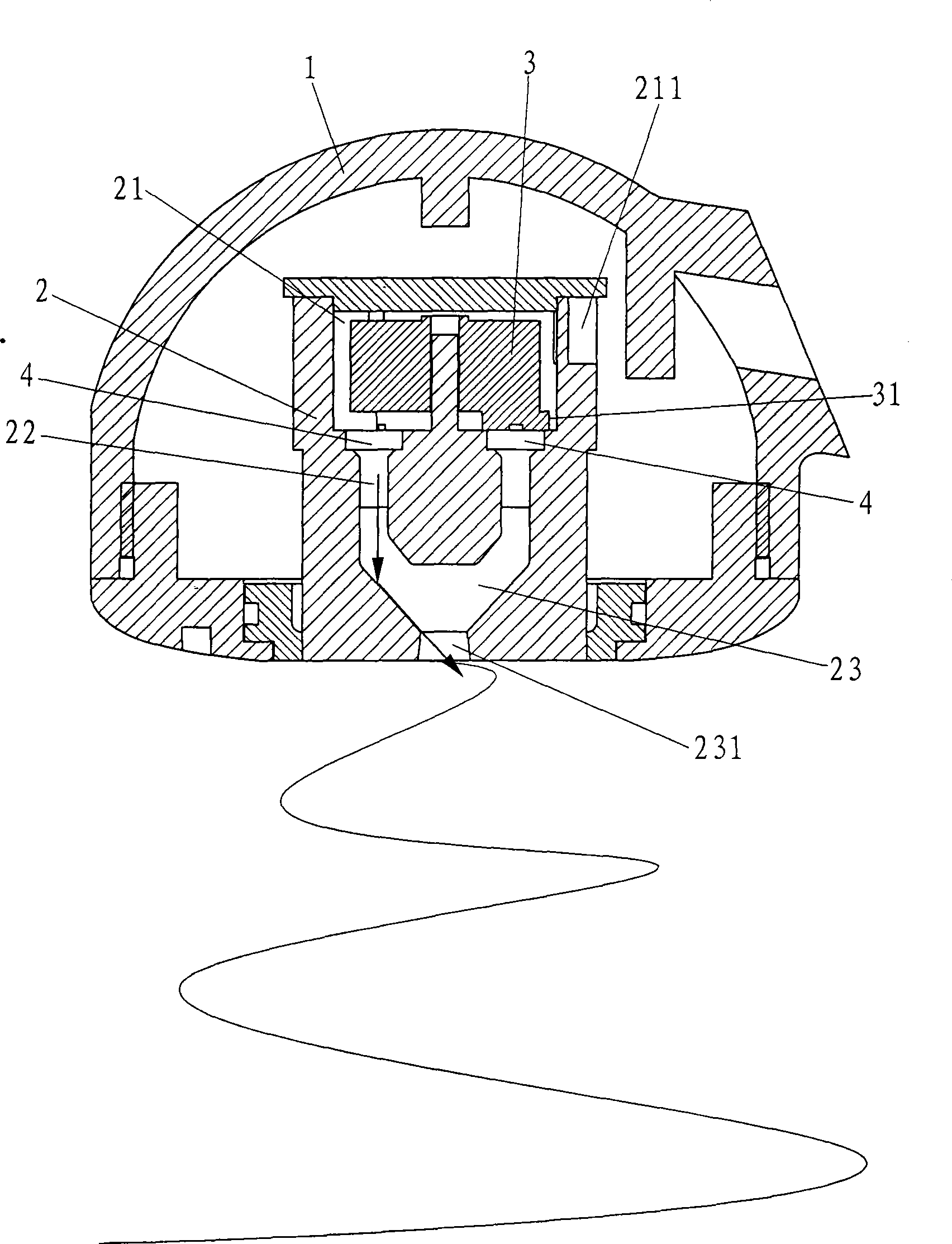
[0015] Such as figure 1 As shown, the present invention relates to a shower. The body 1 of the shower is provided with a cavity 2. The upper part of the cavity 2 forms an impeller cavity 21, the middle part forms an annular cavity 22, and the lower part forms an inverted cone collision. Cavity 23. in:

[0016] The impeller chamber 21 is provided with an impeller 3, one side of which is provided with a water inlet facing the blades of the impeller 3, the water inlet can be an oblique water inlet 211, and several protruding platforms facing the annular chamber 22 are provided below the impeller 3 31.

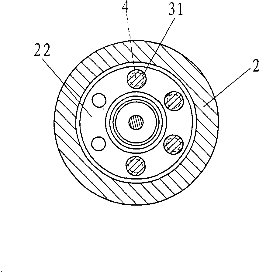
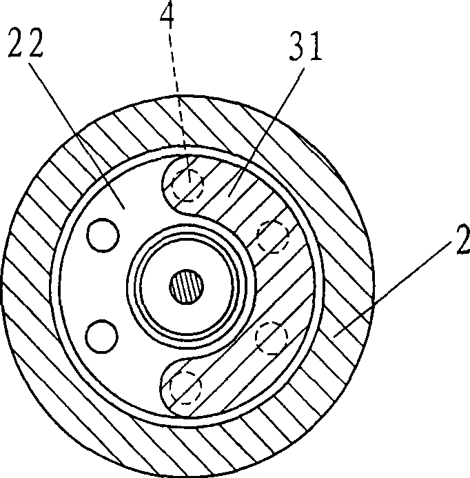
[0017] Said annular cavity 22 upper annular surface place is provided with some ejection ports 4, and above-mentioned several bosses 31 have blocked one or more in these several ejection ports 4 (as figure 2 shown).

[0018] A water outlet 231 is opened at the bottom of the collision chamber 23, and the water outlet 231 is the final water outlet of the shower.

[0019] The w...


PUM


Abstract

The invention discloses a water-saving shower head. A body of the shower head is provided with a cavity body, the upper part of the cavity body forms an impeller cavity, and the lower part of the cavity forms an inverse conical colliding cavity; the inside of the impeller cavity is provided with an impeller, one side of the impeller cavity is provided with a water inlet opposite to a vane of the impeller, the lower part of the impeller is provided with a jet orifice opposite to an inverse conical inclined plane of the colliding cavity, and the jet orifice is driven by the impeller to rotate; and the bottom of the colliding cavity is provided with a water outlet. The water-saving shower head has structural improvement that the shower head is provided with only one water outlet, and the interior jet orifice has only little outflow water at each moment, so as to reduce flow capacity and achieve the aim of saving water. While the colliding cavity can make water jetted out obliquely, periodical rotation of the jet orifice changes to make the final outflow water present periodical multi-angle change, so as to form dense scattered large-particle spray, and the shower bath feeling is the same as the feeling of the prior shower head.

Description

technical field [0001] The invention relates to sanitary equipment, in particular to a water-saving shower. Background technique [0002] At present, the water outlet method of showers on the market has been finalized. Shower water is the most commonly used, but there are a large number of water outlets on the shower, and the continuous water outlet method uses a huge amount of water. Therefore, products in the American market require additional water-saving sheets to limit the flow. Some The purpose of restricting the flow is also achieved by reducing the water outlet. However, although the flow rate is reduced with the setting of the water-saving sheet, the water discharge force is also reduced at the same time; and for the method of reducing the water outlet, the flow rate is reduced, but the water flowing out is relatively sparse. In other words, no matter how the flow is restricted, the shower will not feel the same as a normal shower. Contents of the invention [0...

Claims


Application Information

Patent Timeline
IPC IPC(8): B05B3/02B05B1/02
Inventor 刘工一李仁忠
Owner 周华松
Why Eureka
Try Eureka