Tool for friction stir welding

A technology of friction stir welding and tools, which is applied in the direction of manufacturing tools, welding equipment, non-electric welding equipment, etc., can solve the problems of increased material cost, increased cost of friction stir welding, expensive equipment investment, etc., to improve processing efficiency and shorten processing time , the effect of improving efficiency

Inactive Publication Date: 2009-04-22
HONDA MOTOR CO LTD
View PDF3 Cites 5 Cited by
  • Summary
  • Abstract
  • Description
  • Claims
  • Application Information

AI Technical Summary

Problems solved by technology

[0010] The disadvantage of the technique disclosed in Patent Document 2 is that the structure of the friction stir welding apparatus is complicated and the equipment investment is expensive because two friction stir welding tools need to be installed in opposite directions
[0011] The technique disclosed in Patent Document 3 leads to an increase in material cost due to the need for an additional lump and thus an increase in the cost of friction stir welding
In addition, since a mechanism for supplying additional lumps is required, the structure of the friction stir welding apparatus is also complicated and equipment investment is expensive

Method used


Image

  • Tool for friction stir welding
  • Tool for friction stir welding
  • Tool for friction stir welding

Examples


no. 1 example

[0096] According to a first embodiment, friction stir welding is performed as follows:

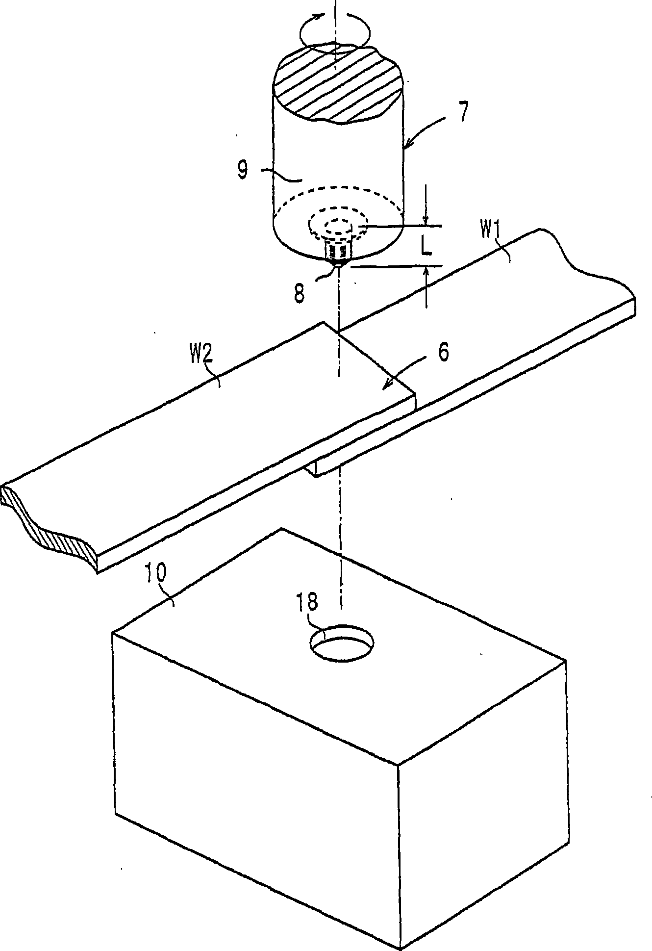
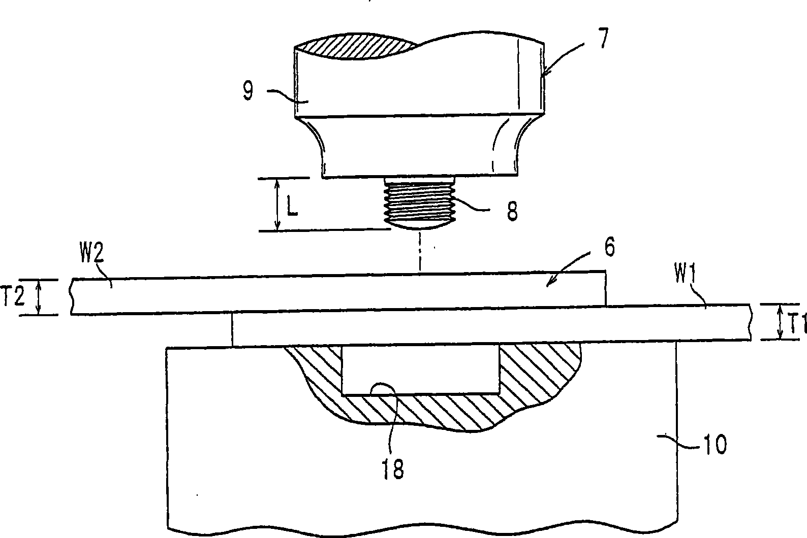
[0097] First, if figure 2 As shown, a first workpiece W1 and a second workpiece W2 are stacked to form a stacked assembly 6 resting on a support fixture 10 . At this point, the stack assembly 6 covers the recess 18 .

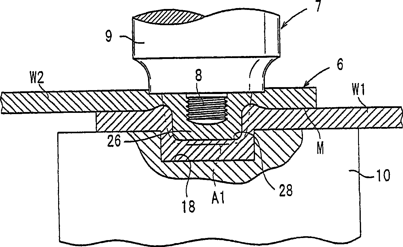
[0098] Then, the friction stir welding tool 7 descends to a position spaced apart from the stack assembly 6 by a predetermined distance. Thereafter, the rotor 9 is rotated so that the probe 8 is brought into sliding contact with the upper end surface of the stack assembly 6 (the upper end surface of the second workpiece W2). When the probe 8 is held in sliding contact with the upper end surface of the stack component 6 , frictional heat is generated to soften the area of ​​the stack component 6 contacted by the probe 8 and the vicinity thereof. results, such as image 3 As shown, the probe 8 is embedded in the stack 6 and the material of the stack 6 flows into the reces...


PUM


Abstract

A recess portion with a substantially circular cross-section is provided in the upper end surface of a supporting jig. When a probe of a device for friction stir welding is buried in the upper end surface of a layered portion, material in the vicinity of the buried portion flows plastically. This causes the plastically flowed material to flow into the recess portion, and as a result, the material is stirred in a relatively large region. When the material that flowed into the recess portion is cooled and solidified, a friction stir-welded portion-possessing member having a projection portion is obtained.

Description

[0001] The present invention is the application number 200480023952.X (PCT / JP2004 / 011144), the application date is August 4, 2004, the title of the invention is "method for friction stir welding and its fixture, parts with friction stir welding parts, and a tool for friction stir welding" is a divisional application of the Chinese invention patent application. technical field [0002] The present invention relates to a friction stir welding method for joining stacked assemblies of stacked parts, a jig for such a friction stir welding method, a component having a friction stir welded joint produced by such a friction stir welding method , and a friction stir welding tool for joining stacked or adjoining assemblies of metal workpieces by friction stir welding. Background technique [0003] Stacked assemblies of components typically rely on spot welding to join them. In recent years, it has been proposed to join such stacked components by friction stir welding (for example, se...

Claims


Application Information

Patent Timeline
Patent Type & Authority Applications(China)
IPC IPC(8): B23K20/12
Inventor 村川敏浩脇坂泰成大久保聪士
Owner HONDA MOTOR CO LTD
Why Eureka
Try Eureka