High back pressure exhaust brake valve with pressure-limiting valve
A technology of exhaust brake valve and pressure limiting valve, which is applied in the direction of engine control, machine/engine, mechanical equipment, etc., can solve the problems of exhaust valve damage, exhaust valve secondary opening, etc., and achieve improved braking power, Optimizing the effect of exhaust back pressure
- Summary
- Abstract
- Description
- Claims
- Application Information
AI Technical Summary
Problems solved by technology
Method used
Image

Examples
Embodiment 1
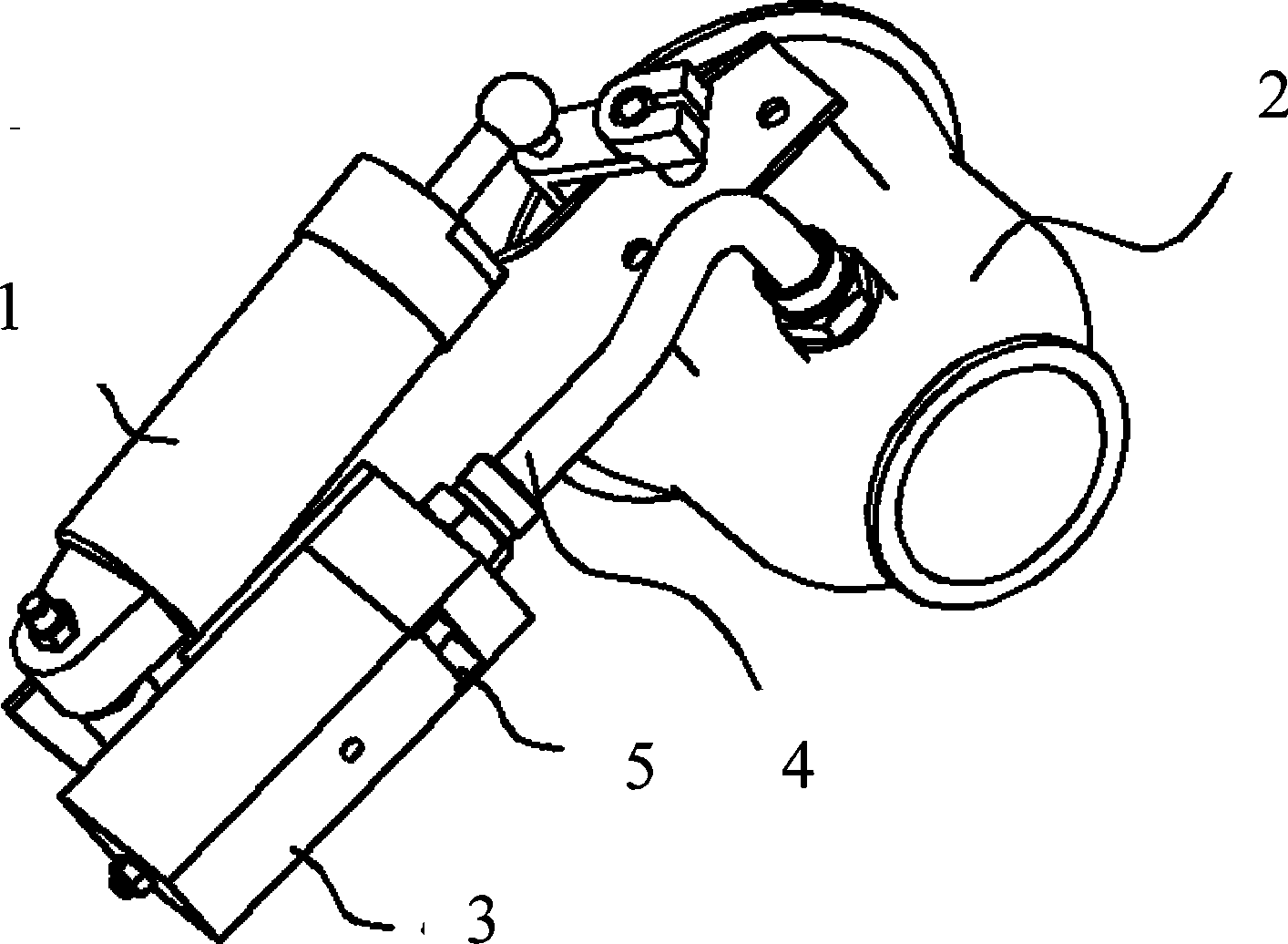
[0017] Such as figure 1 It can be seen that the high back pressure exhaust brake valve with a pressure limiting valve includes a cylinder 1 and an exhaust brake valve 2, and the cylinder 1 and the exhaust brake valve 2 are installed together, and it is characterized in that it also includes a limiter The pressure valve 3 and the connecting pipe 4, the pressure limiting valve 3 is connected with the exhaust brake valve 2 through the connecting pipe 4, and the pressure limiting valve 3 is provided with an exhaust hole 5.
[0018] When the exhaust brake valve works, cylinder 1 works, rotates the butterfly valve to the closed position, and the exhaust pipe is blocked. At this time, due to the low engine speed, the exhaust back pressure is also low, and enters the pressure limit through the connecting pipe 4 The exhaust pressure of valve 3 is not enough to open the pressure limiting valve. As the speed of the engine increases, the exhaust back pressure gradually increases. When it...
Embodiment 2
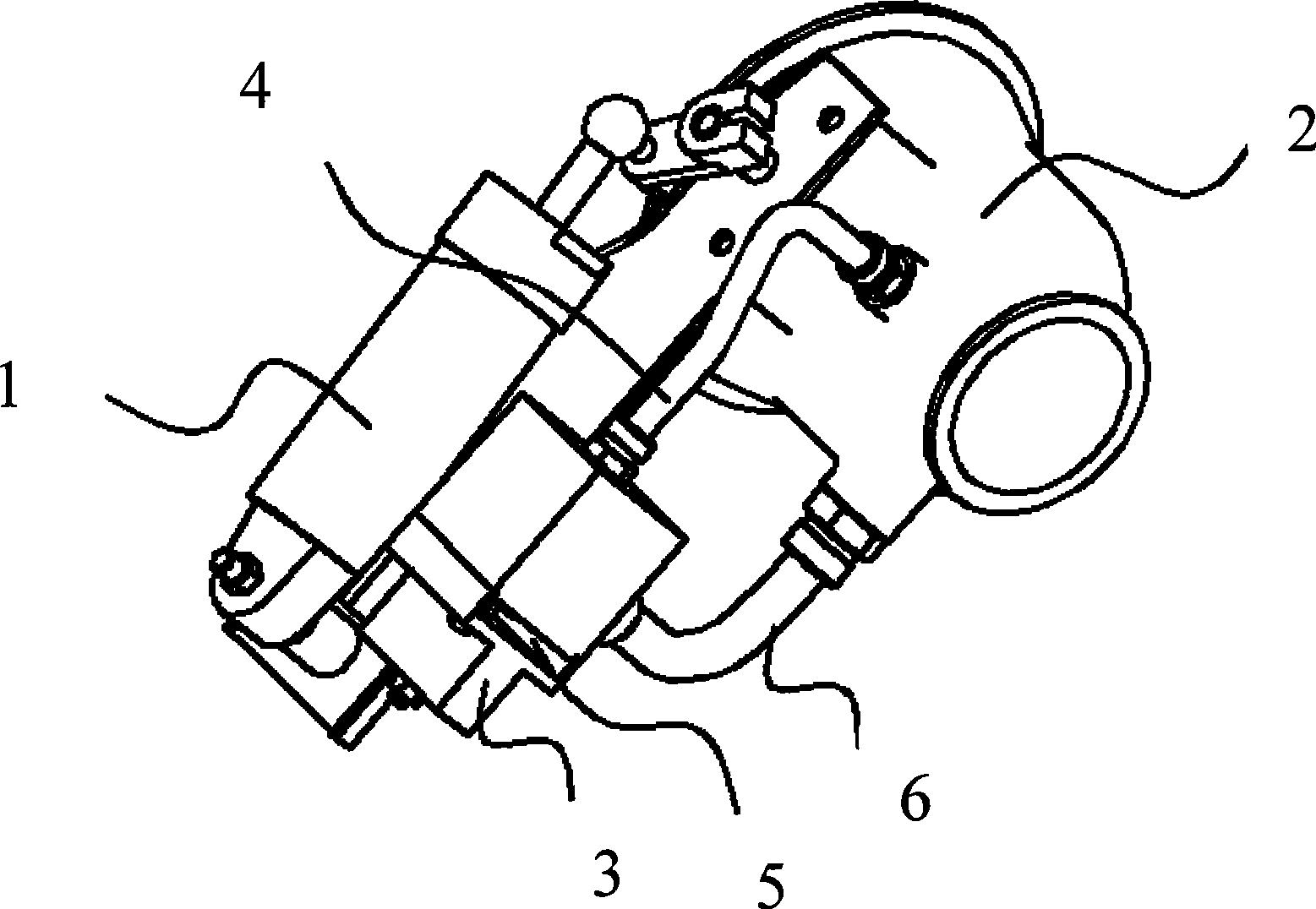
[0020] Such as figure 2 It can be seen that the pressure limiting valve 3 of the present invention is connected with the exhaust brake valve 2 through the connecting pipe 4 and the connecting pipe 6, the connecting pipe 4 provides the pressure source for the pressure limiting valve 3, and the connecting pipe 6 provides the exhaust gas for the pressure limiting valve 3 source. The advantage of this structure is that it can provide a stable and more accurate pressure source, which simplifies the calculation and selection of the spring.
Embodiment 3
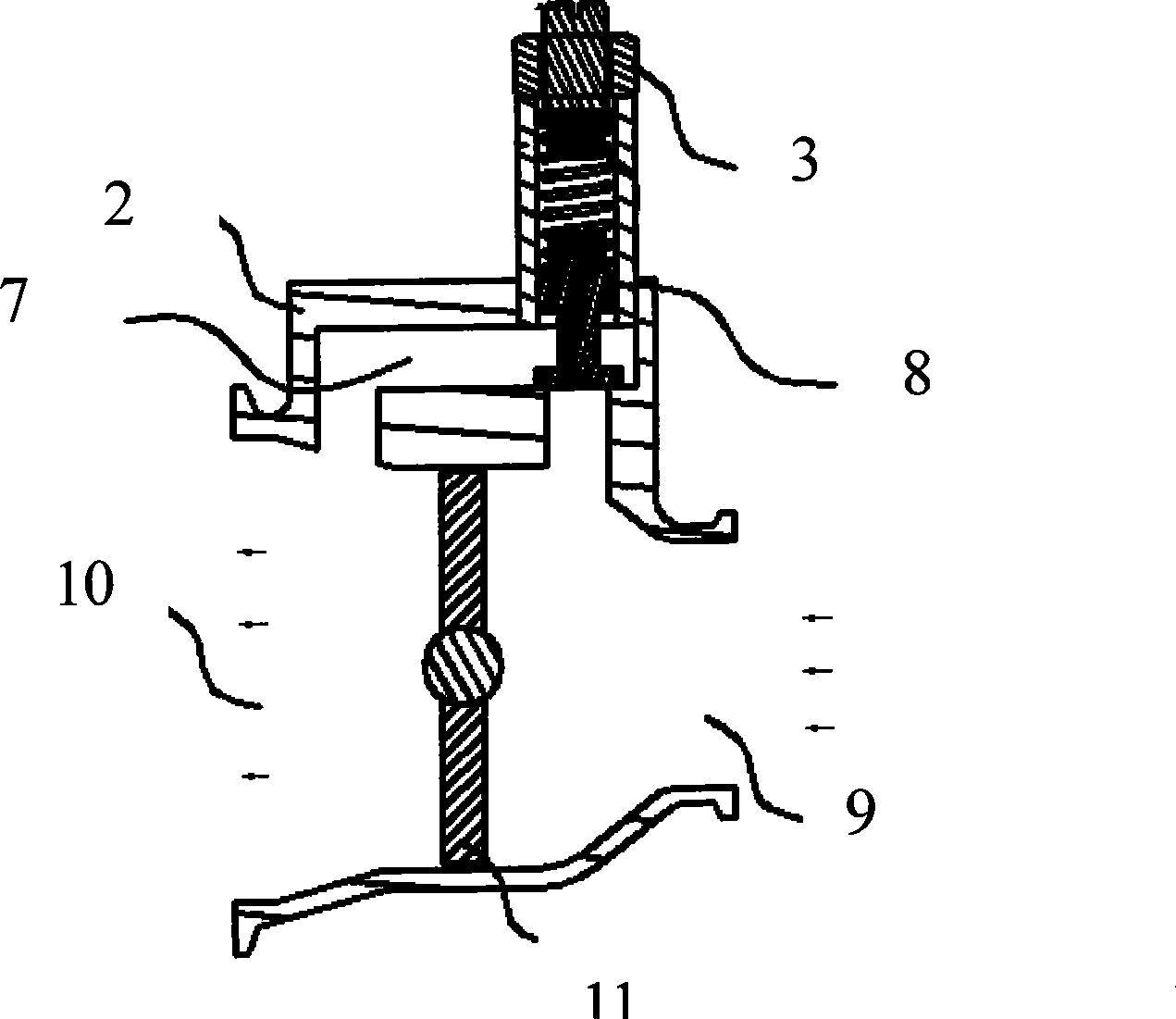
[0022] Such as image 3 It can be seen that the pressure limiting valve 3 of the present invention is integrated with the exhaust brake valve 2, the valve body of the pressure limiting valve 3 is integrated with the valve body of the exhaust brake valve, and the valve body of the exhaust brake valve is provided with a bypass The inlet of the bypass passage communicates with the exhaust inlet 9 of the exhaust pipe of the exhaust brake valve and is sealed by the pressure limiting valve 3, and the outlet of the bypass passage communicates with the exhaust pipe of the exhaust pipe of the exhaust brake valve. Exit 10 is connected.
[0023] The pressure limiting valve 3 can also be manufactured separately.
[0024] The structure of the present invention is not limited to the above three, and its essence is to add a pressure limiting valve to the exhaust brake valve of the engine, or to directly manufacture the pressure limiting valve and the exhaust brake valve into one body. The ...
PUM
 Abstract
Description
Claims
Application Information
 - R&D
- Intellectual Property
- Life Sciences
- Materials
- Tech Scout
- Unparalleled Data Quality
- Higher Quality Content
- 60% Fewer Hallucinations
Browse by: Latest US Patents, China's latest patents, Technical Efficacy Thesaurus, Application Domain, Technology Topic, Popular Technical Reports.
© 2025 PatSnap. All rights reserved.Legal|Privacy policy|Modern Slavery Act Transparency Statement|Sitemap|About US| Contact US: help@patsnap.com