Inserting circuit breaker

A circuit breaker and plug-in technology, which is applied in the direction of circuit breaker components, circuits, electrical components, etc., can solve problems such as poor contact and deformation of plug-in terminals, and achieve the effect of cheap assembly, easy assembly, and high contact reliability

Inactive Publication Date: 2009-04-22
MITSUBISHI ELECTRIC CORP
View PDF1 Cites 18 Cited by
  • Summary
  • Abstract
  • Description
  • Claims
  • Application Information

AI Technical Summary

Problems solved by technology

Therefore, the insertion terminal may be deformed due to excessive load, resulting in poor contact.

Method used


Image

  • Inserting circuit breaker
  • Inserting circuit breaker
  • Inserting circuit breaker

Examples


no. 1 Embodiment approach

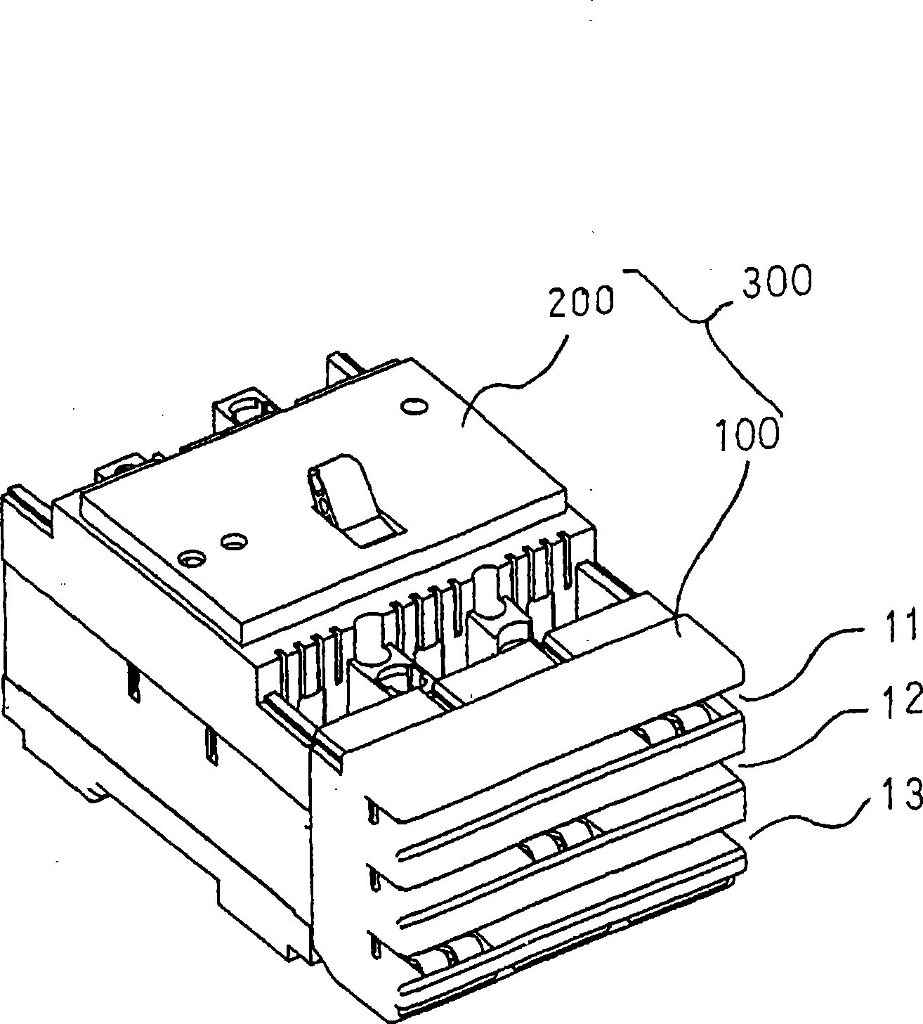
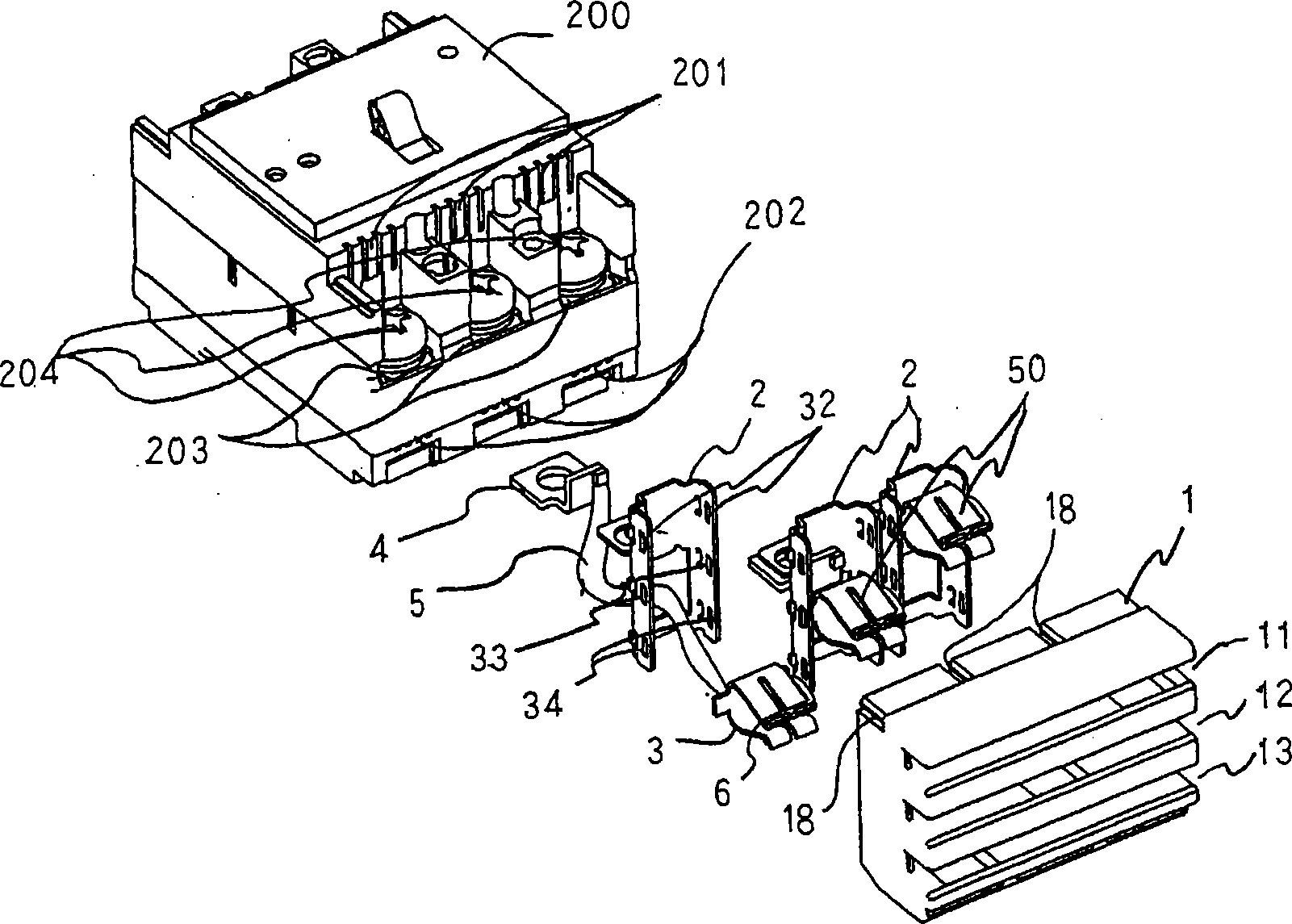
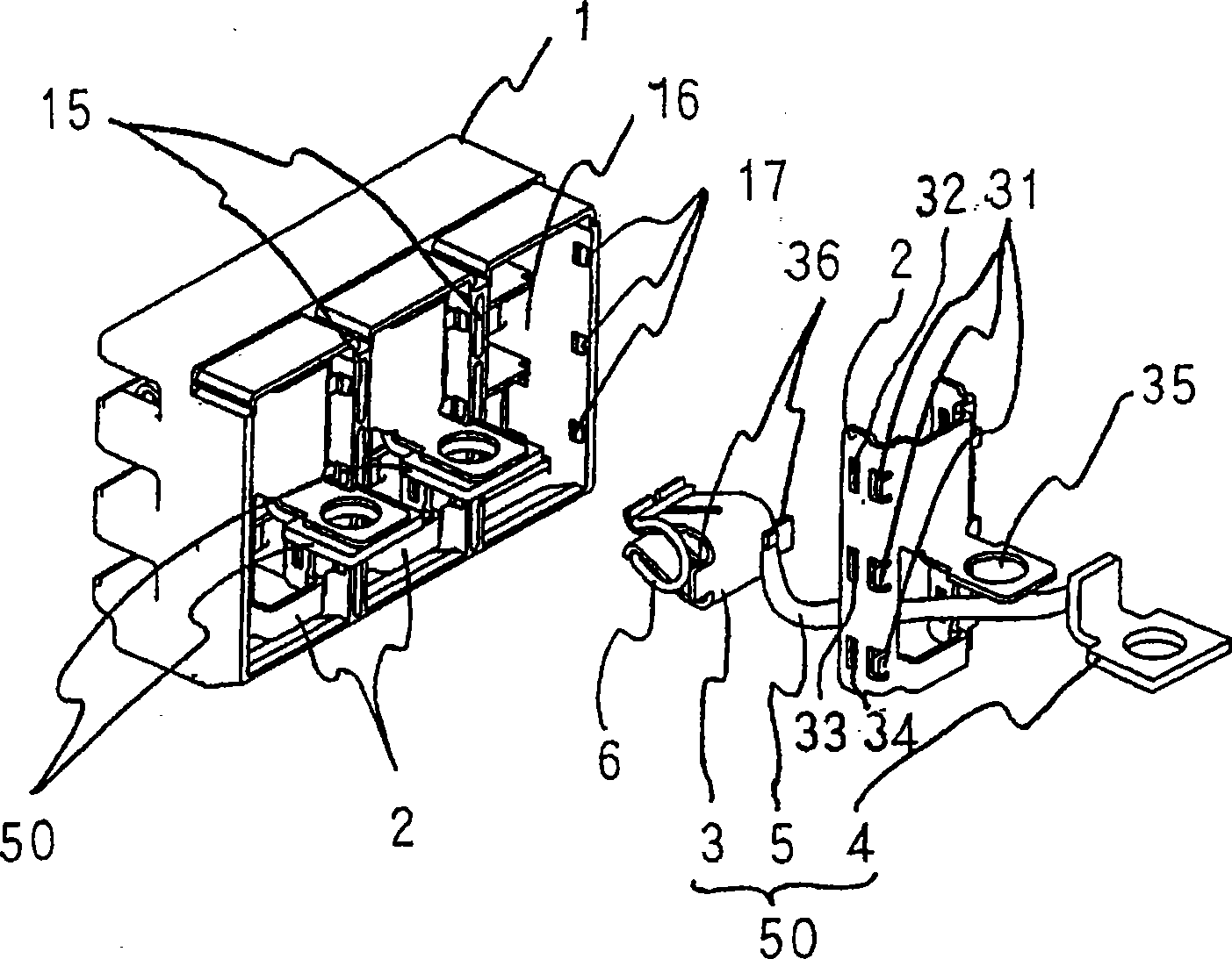
[0019] Figure 1~4 It is a figure for explaining the plug-in type circuit breaker in 1st Embodiment of this invention, figure 1 is an oblique view of a plug-in circuit breaker, figure 2 is its exploded oblique view, image 3 is an exploded oblique view of the plug adapter, which is part of the plug-in circuit breaker, Figure 4 yes figure 1 The sectional view of the main part, (a) shows the bus bar before insertion, and (b) shows the contact state of the bus bar and the inserted terminal. Such as figure 1 As shown, a plug-in circuit breaker 300 is composed of a circuit breaker body 200 and a plug adapter 100 . On the front surface of the plug adapter 100, insertion grooves 11 to 13 for inserting bus bars are arranged in parallel at equal intervals. plug adapter 100 with figure 2 The bolt connection terminals 203 of the illustrated circuit breaker body 200 are fastened by bolts so as to be combined with the circuit breaker body 200 .

[0020] The plug adapter 100 i...

no. 2 Embodiment approach

[0037] pass Figure 5 (a) and 5(b) describe the second embodiment of the present invention. Such as Figure 5 As shown in (a) and 5(b), in the second embodiment, a terminal cover 7 is provided to cover the connecting bolt 204 connecting the plug adapter 100 and the circuit breaker main body 200 . Other structures are the same as those of the first embodiment. The same reference numerals are assigned to the same configurations as those of the first embodiment, and description thereof will be omitted.

[0038] The terminal cover 7 is, for example, a component made of resin bent on both sides, and its upper surface is laser printed 8 or a nameplate is attached to indicate which bus bar each pole of the plug-in circuit breaker is connected to. The terminal cover 7 fits its bent portion into the mounting groove 18 provided on the top of the plug box 1 (refer to figure 2 , Figure 5 (b)) and install it.

[0039] According to the second embodiment, the terminal cover 7 is inst...

no. 3 Embodiment approach

[0046] pass Image 6 (a), 6(b) describe the 3rd embodiment of this invention. Such as Image 6 As shown in (a) and 6(b), in the third embodiment, the plug adapter 100 and / or the terminal cover 7 are respectively provided with exhaust ports 41 and 42 . In this case, exhaust ports 42 are provided for each of the three electrodes in the lower part of the plug box 1 of the plug adapter 100 . On the other hand, the terminal cover 7 is also provided with exhaust ports 41 for three electrodes. Other configurations are the same as those of the first and second embodiments. The same reference numerals are assigned to the same configurations as those of the first embodiment and the second embodiment, and description thereof will be omitted.

[0047] Such as figure 2 As shown, the main body 200 of the circuit breaker is provided with an upper exhaust port 201 and a lower exhaust port 202 for discharging smoke and dust during circuit breaker. According to this third embodiment, the...


PUM


Abstract

The invention relates to a plug-type circuit breaker with few parts, good assembly operational performance, uneasily deformed plug-in terminal and high contact reliability. The plug-type circuit breaker is formed by connecting a plug adaptor and a circuit breaker main body bolts with a bolt connecting terminal. In the plug-type circuit breaker, a plug box is internally installed with: the plug-in terminal connected with any one of multiple bus poles by plugging in; and a socket mechanically connected with the circuit breaker main body. In the plug adaptor, a pair of convex parts is integrally formed on the plug-in terminal. A plug-in terminal mounting part composed of an opening is formed on the socket. At the same time, the plug-in terminal is electrically connected with the circuit breaker main body by a branch current conductor. The opening is actively embedded with the convex parts to support the plug-in terminal so that the plug-in terminal can rotate in a direction orthogonal to the bus poles.

Description

technical field [0001] This invention relates to circuit breakers, and more particularly to plug-in type circuit breakers. Background technique [0002] In conventional circuit breakers, claws made of elastic metal provided on the mounting plate of the circuit breaker are usually installed into locking holes provided under the rear end of the plug-in circuit breaker by utilizing its elasticity. However, since the installation to the circuit breaker mounting plate is performed simultaneously with inserting the plug-in terminals into the bus bar, it is necessary to press the rear end side of the plug-in circuit breaker from above the circuit breaker mounting plate so that the plug-in terminals Insert it obliquely upward to fit with the bus bar. Therefore, there is a possibility that the insertion terminal is deformed due to an excessive load, resulting in poor contact. [0003] On the other hand, in order to prevent deformation of the insertion terminal due to height positio...

Claims


Application Information

Patent Timeline
Patent Type & Authority Applications(China)
IPC IPC(8): H01H71/08H01H73/20H01R9/22H01R4/48H02B1/20
Inventor 信太秀夫山中尚细贝节夫
Owner MITSUBISHI ELECTRIC CORP
Why Eureka
Try Eureka