
Seat belt retractor and seat belt apparatus employing the same

A seat belt retractor and seat belt technology, which is applied in the directions of seat belts, belt tensioners, and energy-absorbing devices in the vehicle, can solve the problem of the increased installation space of the seat belt retractor 3 and the difficulty in rolling the seat belts. The compactness of the receiver 3 requires the requirements of the interior space of the vehicle, etc., to prevent the limit load from increasing rapidly, the structure is simple, and the axial length is shortened.

Inactive Publication Date: 2012-12-26
JOYSON SAFETY SYST JAPAN KK
View PDF2 Cites 0 Cited by
  • Summary
  • Abstract
  • Description
  • Claims
  • Application Information

AI Technical Summary

Problems solved by technology

However, if the size of the seat belt retractor 3 is increased as described above, the mounting space of the seat belt retractor 3 is also increased, so that it is difficult to sufficiently and flexibly realize the compactness of the seat belt retractor 3 . requirements and the requirements for the interior space of the vehicle

Method used


Image

  • Seat belt retractor and seat belt apparatus employing the same
  • Seat belt retractor and seat belt apparatus employing the same
  • Seat belt retractor and seat belt apparatus employing the same

Examples


Embodiment Construction

[0044] DETAILED DESCRIPTION OF THE PREFERRED EMBODIMENTS The best embodiments for carrying out the present invention will be described below using the drawings.

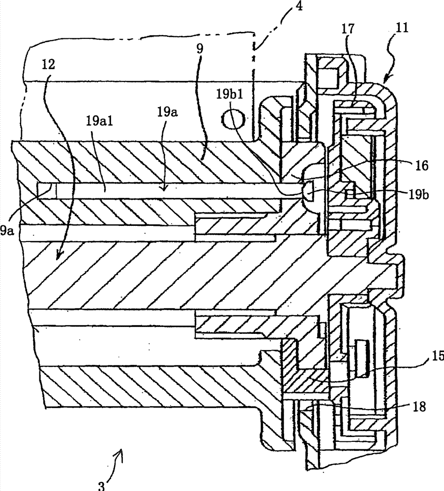
[0045] figure 1 It is a view which schematically and partly shows the seatbelt retractor which concerns on one Embodiment of this invention. In describing the embodiments below, the same reference numerals are used to denote the same structural components as those of the above-described prior art example, and detailed description is omitted.

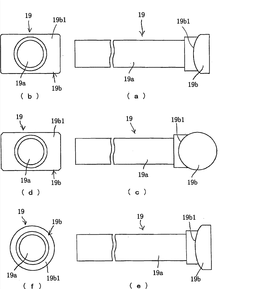
[0046] Such as figure 1 As shown, the safety belt retractor 3 of this example is the same as the above-mentioned Image 6 Same as the prior art example shown, the energy absorbing pin 19 passes through the locking base 16 and the portion 19a1 of the shaft portion 19a fits into the axial hole 9a of the spool 9 . Such as figure 2 As shown in (a), the shaft portion 19a of the energy absorbing pin 19 of this example is formed in a linear shape and protrudes perpendicularly f...


PUM


Abstract

To further facilitate the operation of assembling an energy absorbing pin and improve the productivity with obtaining stable limited load, a head portion (19b) of an energy absorbing pin (19) has a contact surface (19b 1 ) which is arc curved surface. In the state that the energy absorbing pin (19) is assembled, the contact surface (19b 1 ) comes in contact with a bottom surface (16a 1 ) of a concavity (16a) of a locking base (16). As a spool (9) rotates in the belt withdrawing direction relative to the locking base (16), the head portion (19b) is subjected to bending force by the locking base (16) in the rotational direction of the locking base (16). Since the contact surface (19b 1 ) is a curved surface, the head portion (19b) easily rotates, thus preventing the limited load from rapidly increasing at the initial stage of drawing action of the energy absorbing pin (19). Therefore, it is possible to prevent the limited load from overshooting at the initial stage of the EA action.

Description

technical field [0001] The present invention relates to a seat belt retractor capable of winding a seat belt, in particular to a seat belt retractor having an energy absorbing mechanism (hereinafter referred to as "EA mechanism") and a seat belt device having the same. When the absorbing mechanism prevents the pull-out of the seat belt when the seat belt is installed and a collision occurs with a large deceleration, the load applied to the seat belt is limited by the action of the energy absorbing member, And absorb and ease the energy of the occupants. Background technique [0002] Conventionally, seat belt devices installed on vehicles such as automobiles use seat belts to restrain occupants in the above-mentioned emergency situations to prevent occupants from flying out of the seats. [0003] Figure 5 It is a view schematically showing a conventional conventional seat belt device. exist Figure 5 Among them, 1 denotes a seat belt device, 2 denotes a vehicle seat, 3 den...

Claims


Application Information

Patent Timeline
Patent Type & Authority Patents(China)
IPC IPC(8): B60R22/28B60R22/34
CPCB60R22/3413B60R2022/287B60R2022/283
Inventor 井浦裕介吉冈宏一亀好光
Owner JOYSON SAFETY SYST JAPAN KK
Learn More