Voltage regulator

a voltage regulator and overshoot technology, applied in the direction of power conversion systems, instruments, process and machine control, etc., can solve the problems of voltage regulators increasing current consumption and excessive overshoot at the output terminal

Active Publication Date: 2016-04-26
ABLIC INC
View PDF10 Cites 8 Cited by
  • Summary
  • Abstract
  • Description
  • Claims
  • Application Information

AI Technical Summary

Benefits of technology

[0011]The present invention has been made in view of the above-mentioned problems, and provides a voltage regulator that is low in current consumption and is capable of suppressing the occurrence of an excessive overshoot at an output terminal when a power supply voltage becomes high in a non-regulated state.
[0014]The voltage regulator including the overshoot suppression circuit according to one embodiment of the present invention has the effect that the current consumption is low and the overshoot of the output voltage that occurs when the power supply voltage becomes high in the non-regulated state can be suppressed.

Problems solved by technology

In the conventional voltage regulator, however, there is a problem in that an excessive overshoot occurs at the output terminal 109 when a power supply voltage becomes higher from a state in which the power supply voltage is low and the output terminal 109 outputs a voltage lower than a predetermined output voltage Vout (hereinafter referred to as “non-regulated state”).
In order to prevent the excessive overshoot, it is necessary to increase the current supplied from the bias circuit 302 for the amplifier 301, and hence there is another problem in that the voltage regulator is increased in current consumption.

Method used


Image

  • Voltage regulator
  • Voltage regulator
  • Voltage regulator

Examples


first embodiment

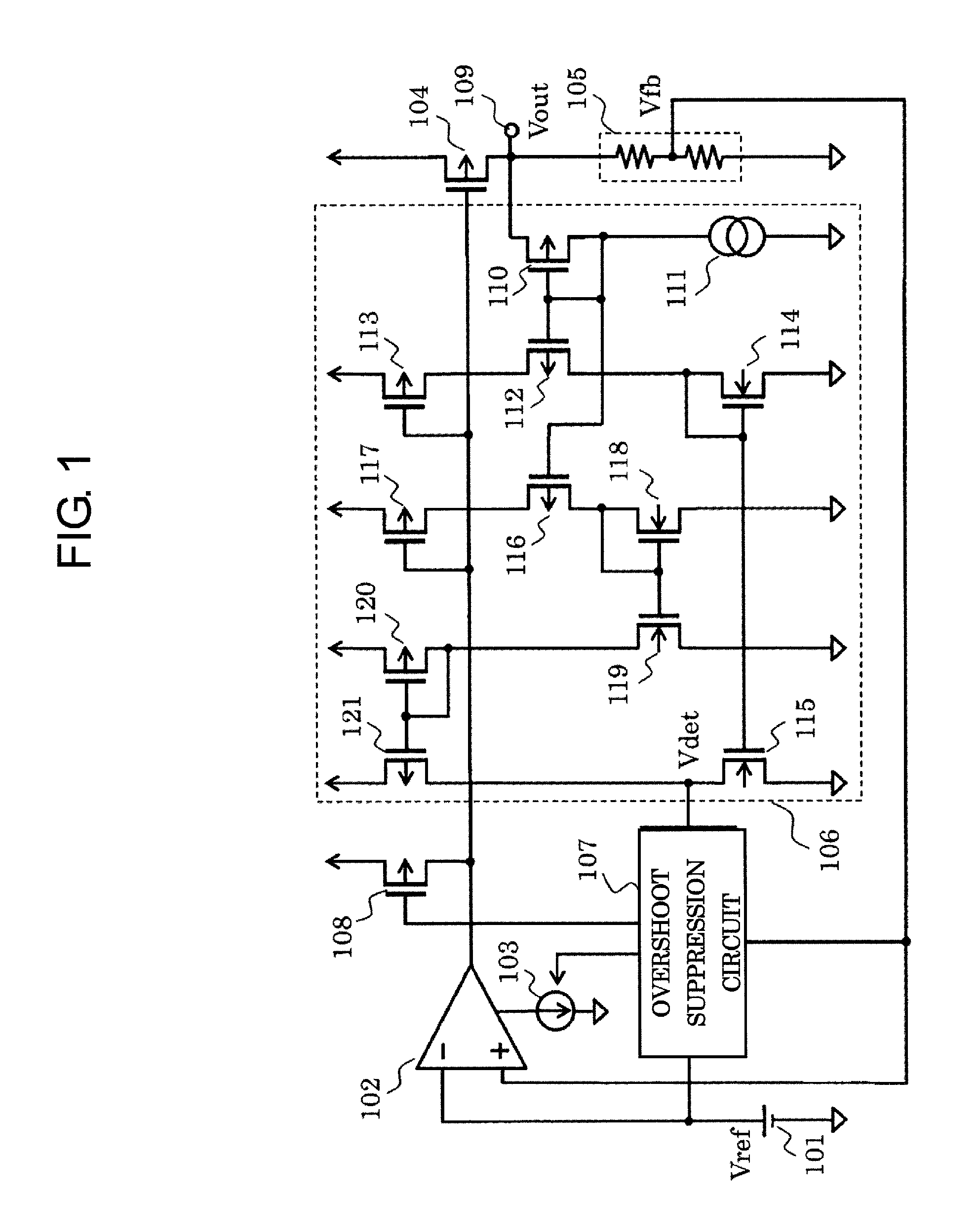
[0021]FIG. 1 is a circuit diagram of a voltage regulator including an overshoot suppression circuit according to a first embodiment of the present invention.

[0022]The voltage regulator according to this embodiment includes a reference voltage circuit 101, an error amplifier circuit 102, a bias circuit 103 for the error amplifier circuit 102, an output transistor 104, a voltage dividing resistor circuit 105, a non-regulated state detection circuit 106, an overshoot control circuit 107, and a PMOS transistor 108. The non-regulated state detection circuit 106 and the overshoot control circuit 107 constitute the overshoot suppression circuit.

[0023]The voltage dividing resistor circuit 105 is connected between an output terminal 109 and a ground terminal. The error amplifier circuit 102 has a non-inverting input terminal for inputting a feedback voltage Vfb and an inverting input terminal for inputting a reference voltage Vref. The output transistor 104 has a gate connected to an output ...

second embodiment

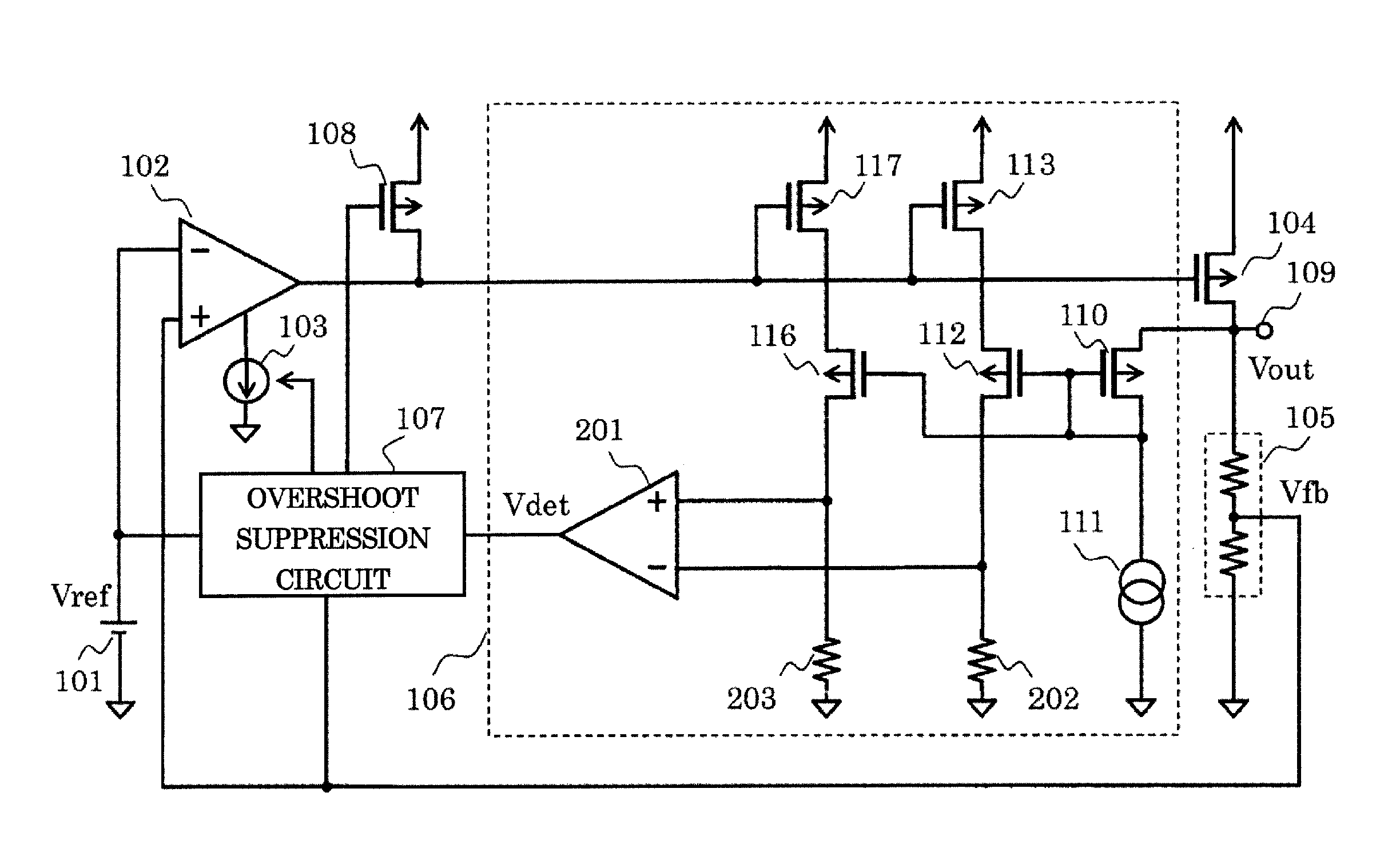
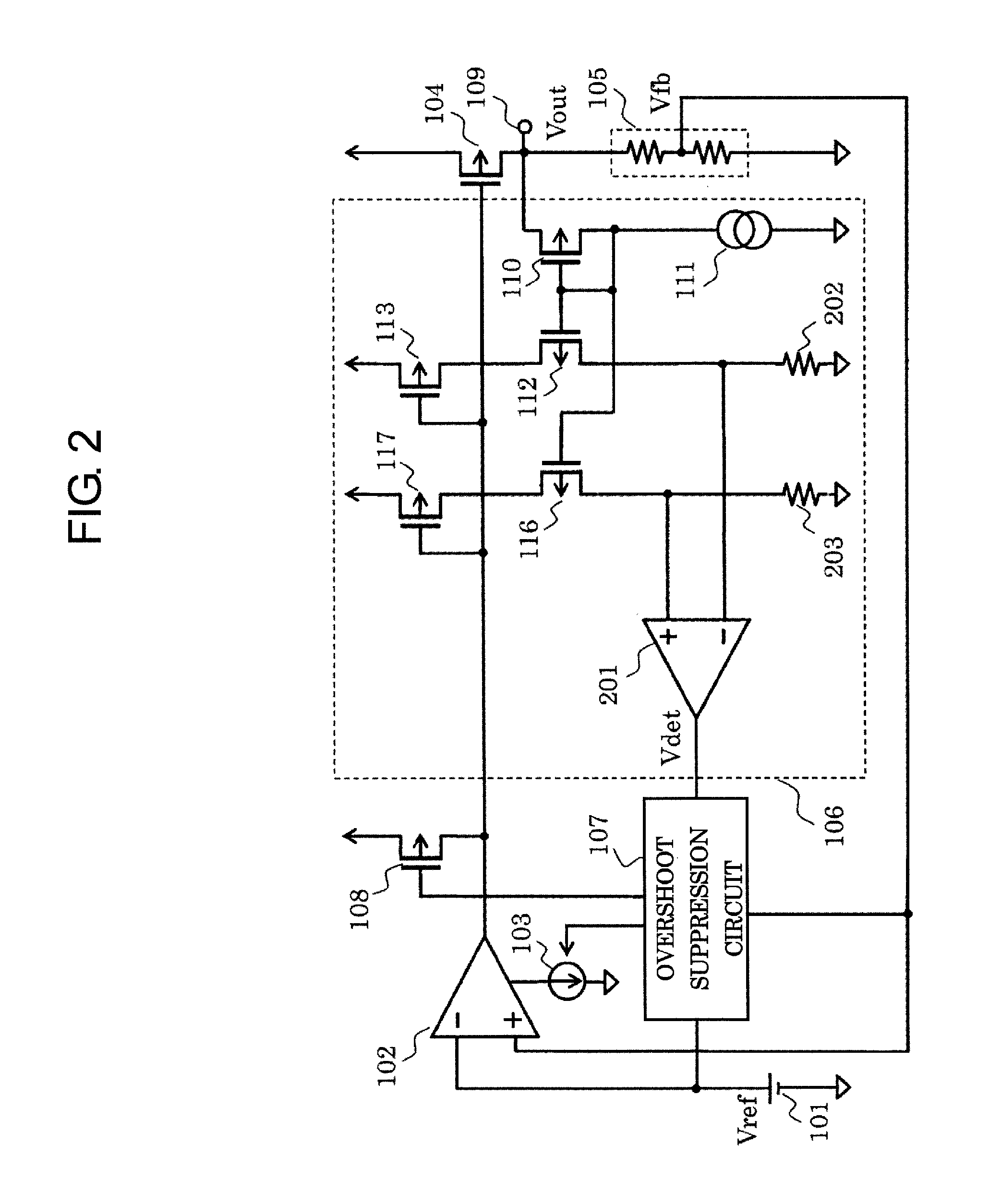
[0040]FIG. 2 illustrates a circuit diagram of a voltage regulator according to a second embodiment of the present invention. In the voltage regulator according to the second embodiment, the non-regulated state detection circuit 106 is configured as follows.

[0041]The first detection circuit is formed of the PMOS transistor 112, the PMOS transistor 113, and a resistor 202. The second detection circuit is formed of the PMOS transistor 116, the PMOS transistor 117, and a resistor 203. An output terminal of a comparator circuit 201 for inputting respective detection results serves as the output terminal of the non-regulated state detection circuit 106.

[0042]Even with this circuit configuration, similar effects as in the first embodiment can be obtained.

[0043]As described above, according to the voltage regulator of this embodiment, in the normal state, an unnecessary current is prevented from flowing through the overshoot suppression circuit, and hence the effect of reducing the current ...


PUM


Abstract

Provided is a voltage regulator that is low in current consumption and is capable of suppressing the occurrence of an excessive overshoot at an output terminal when a power supply voltage becomes high in a non-regulated state. The voltage regulator includes: an overshoot limiting circuit for detecting an occurrence of an overshoot in an output voltage and limiting a current of the output transistor; and a non-regulated state detection circuit for detecting a non-regulated state of the voltage regulator based on a voltage of an output terminal and a current flowing through the output transistor. The overshoot limiting circuit has an operating current controlled by a detection signal of the non-regulated state detection circuit.

Description

RELATED APPLICATIONS[0001]This application is a continuation of PCT / JP2013 / 068815 filed on Jul. 10, 2013, which claims priority to Japanese Application No. 2012-197541 filed on Sep. 7, 2012. The entire contents of these applications are incorporated herein by reference.BACKGROUND OF THE INVENTION[0002]1. Field of the Invention[0003]The present invention relates to an overshoot suppression circuit for a voltage regulator.[0004]2. Description of the Related Art[0005]A conventional voltage regulator is now described. FIG. 4 is a circuit diagram illustrating the conventional voltage regulator.[0006]The conventional voltage regulator includes a reference voltage circuit 101, an error amplifier circuit 102, a bias circuit 103 for the error amplifier circuit 102, a PMOS transistor 104 serving as an output transistor, a voltage dividing resistor circuit 105, an amplifier 301, a bias circuit 302 for the amplifier 301, and a PMOS transistor 108.[0007]The PMOS transistor 104 is connected betwe...

Claims


Application Information

Patent Timeline
Patent Type & Authority Patents(United States)
IPC IPC(8): G05F1/569G05F1/575H02M1/32G05F1/56G05F1/10
CPCG05F1/10H02M1/32G05F1/56G05F1/575
Inventor NAKASHIMO, TAKAOKUROZO, TADASHI
Owner ABLIC INC
Why Eureka
Try Eureka