Drive method for brushless motor and drive control apparatus therefor

a technology of drive control and brushless motor, which is applied in the direction of motor/generator/converter stopper, electronic commutator, dynamo-electric converter control, etc., can solve the problems of heat or noise, electric type has problems in steerability and environmental immunity, and the region in which efficiency is reduced or the consumption current appears to increase, so as to increase the efficiency of the brushless motor and reduce the consumption current

Active Publication Date: 2007-01-02
MITSUBISHI ELECTRIC CORP
View PDF7 Cites 29 Cited by
  • Summary
  • Abstract
  • Description
  • Claims
  • Application Information

AI Technical Summary

Benefits of technology

[0011]This invention has been made in order to solve the problems of the prior-art control techniques as stated above, and has for its object to provide a drive method for a brushless motor and a drive control apparatus therefor as can attain the high efficiency of the brushless motor and decrease the consumption current thereof especially in a low-speed revolution region and a high-load region.
[0015]According to this invention, there are provided a drive method for a brushless motor and a drive control apparatus therefor in which, especially in the low-speed revolution region and high-load region of the brushless motor, an efficiency is high, and a consumption current can be decreased.

Problems solved by technology

On the other hand, however, the electric type has problems in the steerability and an environmental immunity including heat or noise.
However, in a case where a variable speed is required, there is such a problem that a region in which an efficiency lowers or a consumed current increases appears.

Method used


Image

  • Drive method for brushless motor and drive control apparatus therefor
  • Drive method for brushless motor and drive control apparatus therefor
  • Drive method for brushless motor and drive control apparatus therefor

Examples


embodiment 1

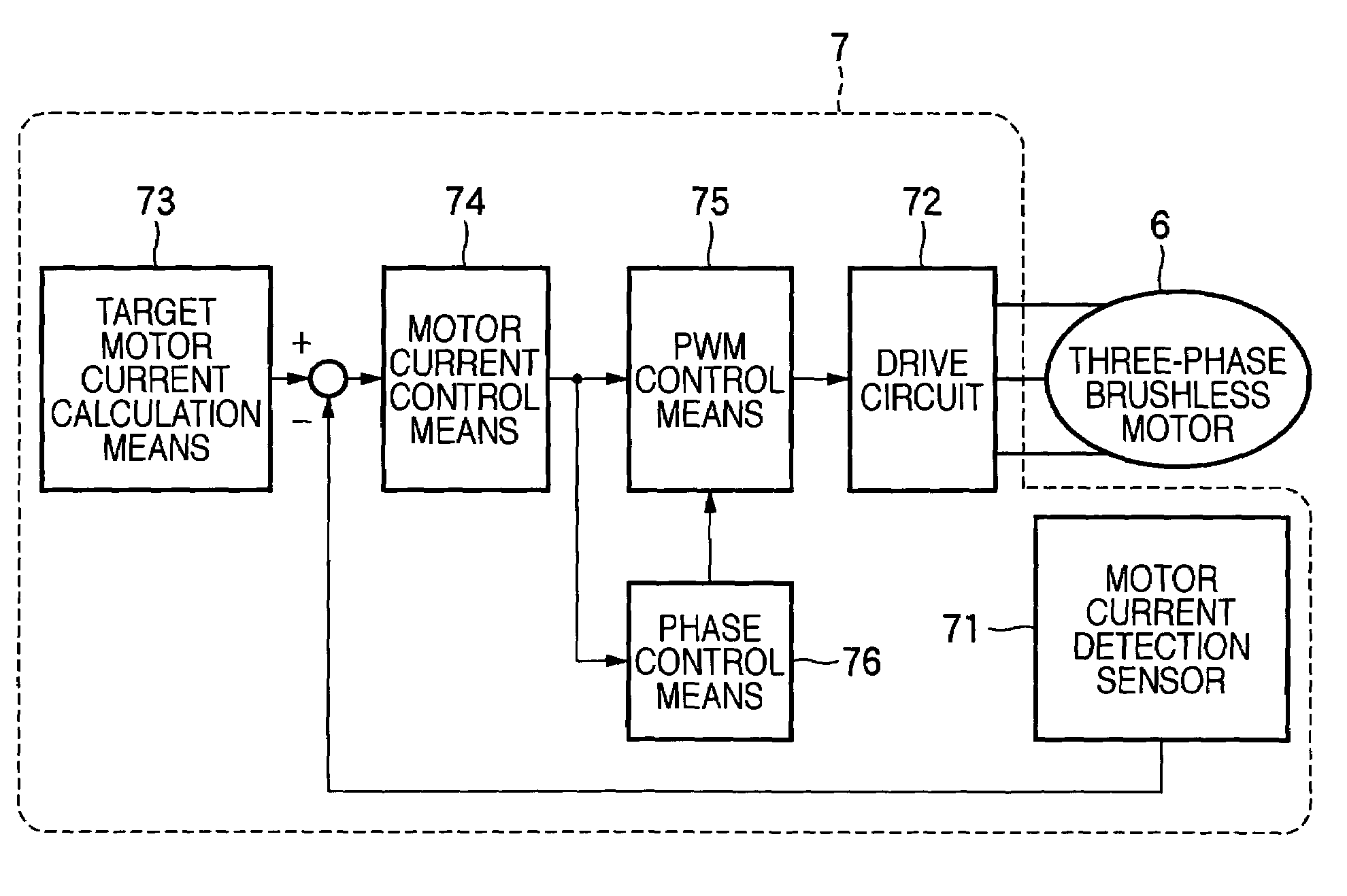
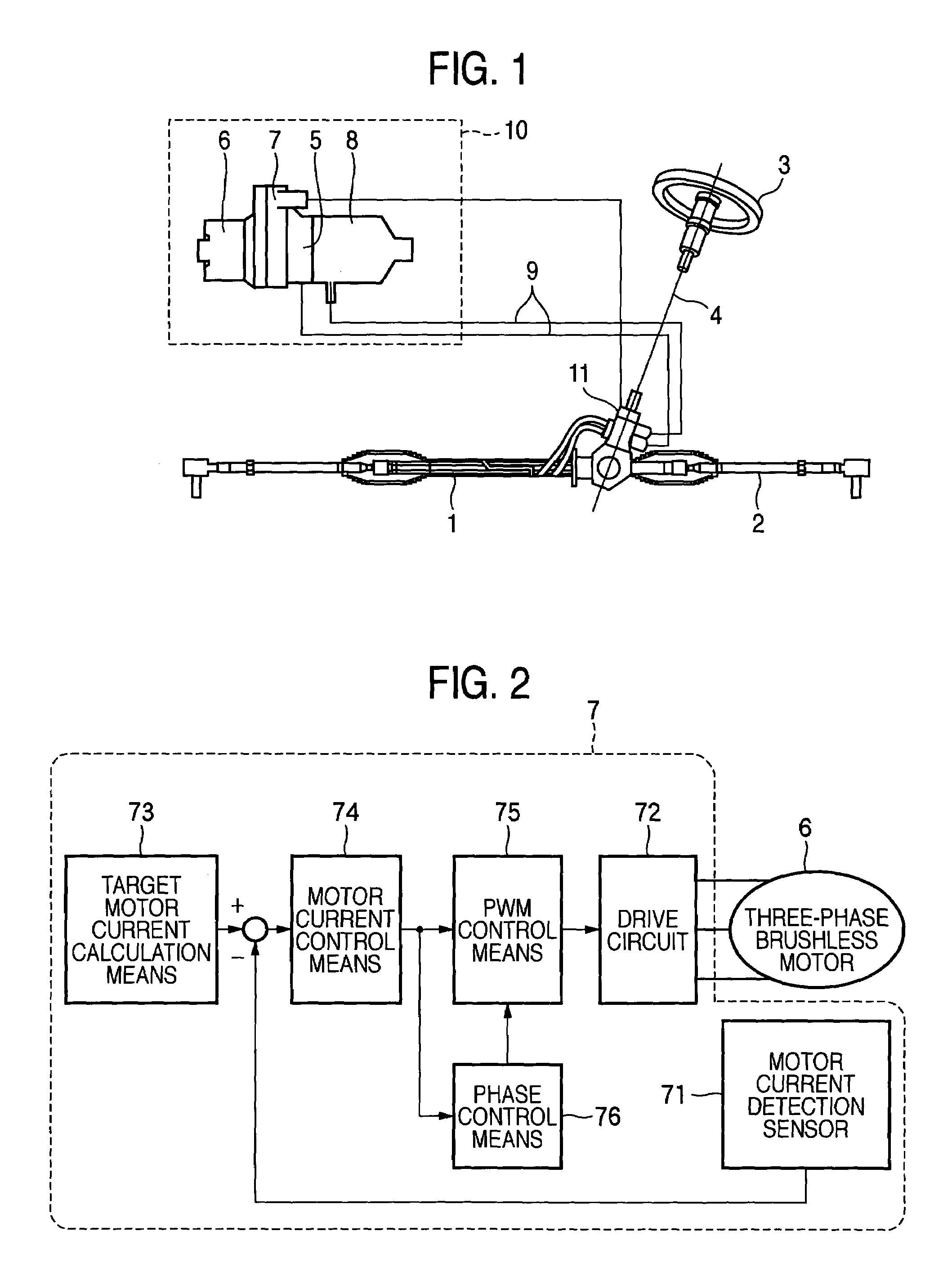
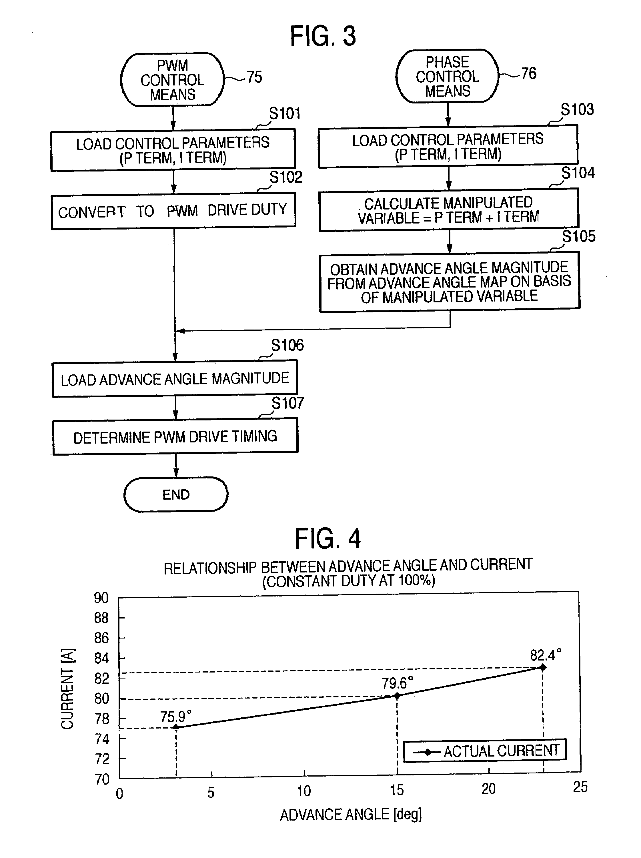
[0022]In general, the control of a motor subjects drive transistors to PWM drive so as to zeroize the deviation between a set target motor revolution number and an actual revolution number. Usually, a PID control (where P denotes a proportion control, I denotes an integration control, and D denotes a differentiation control) is performed in accordance with the deviation. With only the PID control, however, the conduction phase angle of a motor drive circuit becomes constant. In order to solve the problems of the prior art as stated above, therefore, the conduction phase angle needs to be controlled using any means.

[0023]In this invention, the conduction phase angle is controlled using control parameters obtained on the basis of the deviation between a target motor current value and an actual motor current value, that is, a P term (proportion term), an I term (integration term) and a D term (differentiation term), whereby a motor efficiency is heightened especially in a low-speed rev...


PUM


Abstract

A drive method for a brushless motor and a drive control apparatus therefor, in which control parameters are calculated by motor current control means (74 in FIG. 2) in accordance with the deviation between a target motor current value and an actual motor current value, a manipulated variable is computed by phase control means (76) on the basis of the calculated control parameters, an advance angle magnitude is computed from the relationship between a manipulated variable and an advance angle magnitude as designed and created beforehand, on the basis of the computed manipulated variable, and the value of the conduction phase angle of a drive circuit (72) as set on the basis of a motor current signal is corrected with the information of the computed advance angle magnitude.

Description

BACKGROUND OF THE INVENTION[0001]1. Field of the Invention[0002]This invention relates to a drive method for a brushless motor and a drive control apparatus therefor. More particularly, it relates to a drive method for a brushless motor and a drive control apparatus therefor as are well suited for application to a hydraulic type power steering control system employing the brushless motor.[0003]This application is an application relevant to U.S. patent application Ser. No. 11 / 311,313 filed on Dec. 20, 2005 (corresponding Japanese Patent Application: Application No. JP2005-145429 filed on May 18, 2005) by the same inventors as in this application.[0004]2. Description of the Related Art[0005]In recent years, power steering control systems each of which assists the driver of a vehicle in handle manipulation have been often used for the steerability and stability of the driver of the vehicle. The power steering control systems include an electric type and a hydraulic type. As compared wi...

Claims


Application Information

Patent Timeline
Patent Type & Authority Patents(United States)
IPC IPC(8): H02P6/08H02P6/06H02P6/15H02P6/28
CPCB62D5/046B62D5/064B62D5/065H02P23/0004H02P6/142H02P25/026H02P6/002H02P2205/01H02P6/28H02P6/15H02P25/03
Inventor NAKAGAWA, AKIHIROSUZUMURA, JUN
Owner MITSUBISHI ELECTRIC CORP
Why Eureka
Try Eureka