Rankine cycle system

a technology of cycle system and cycle, which is applied in the direction of steam engine plants, machines/engines, mechanical equipment, etc., can solve the problems of deteriorating the operating efficiency of the expander, automobile giving an uncomfortable feeling to the driver, etc., and achieves the effect of increasing the energy of the exhaust gas and good responsiveness

Inactive Publication Date: 2006-09-14
HONDA MOTOR CO LTD
View PDF4 Cites 11 Cited by
  • Summary
  • Abstract
  • Description
  • Claims
  • Application Information

AI Technical Summary

Benefits of technology

[0008] The present invention has been accomplished under the above-mentioned circumstances, and it is an object thereof to carry out control with good responsiveness so that the temper...

Problems solved by technology

Thus, the steam temperature might overshoot the target temperature to deteriorate the operating efficiency of the expander.
However, if cylinder shut-off is carri...

Method used


Image

  • Rankine cycle system
  • Rankine cycle system
  • Rankine cycle system

Examples


Embodiment Construction

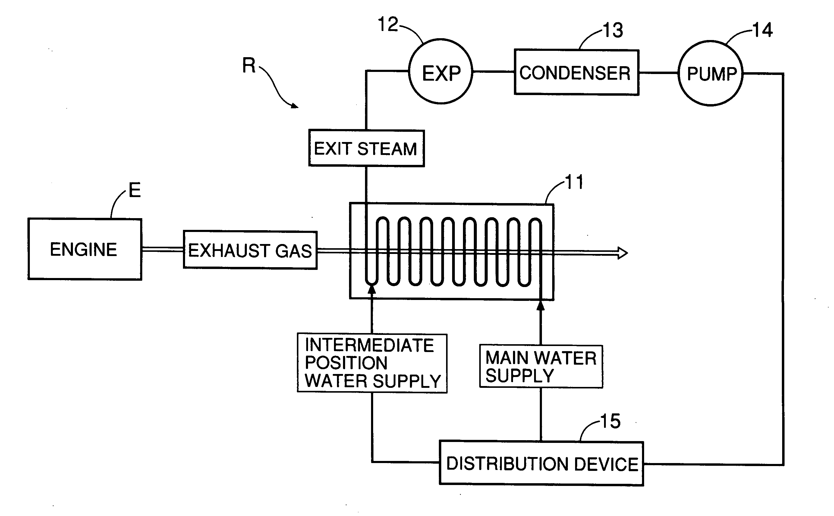
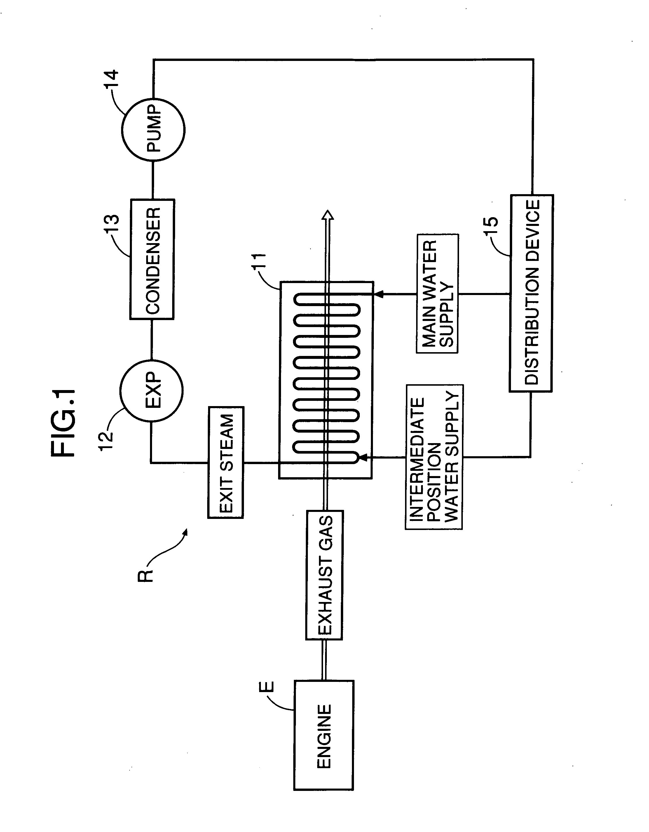
[0030]FIG. 1 shows the overall arrangement of a Rankine cycle system R to which the present invention is applied. The Rankine cycle system R recovers thermal energy of exhaust gas of an engine E and converts it into mechanical energy. The Rankine cycle system R includes: an evaporator 11; an expander 12; a condenser 13; a water supply pump 14; and a distribution device 15 for water supplied from the pump 14 to the evaporator 11. The evaporator 11 heats water with the exhaust gas discharged by the engine E so as to generate high temperature, high pressure steam. The expander 12 is operated by the high temperature, high pressure steam generated by the evaporator 11 so as to generate mechanical energy. The condenser 13 cools decreased temperature, decreased pressure steam that has completed work in the expander 12 so as to turn it back into water. The water supply pump 14 pressurizes water discharged from the condenser 13 and supplies it to the evaporator 11 again. Supply of water to t...


PUM


Abstract

A Rankine cycle system includes: an evaporator for heating water with thermal energy of exhaust gas of an engine so as to generate steam; an expander for converting the thermal energy of the steam generated by the evaporator into mechanical energy; and a distribution device for manipulating the amount of water supplied to the evaporator in order to make the temperature of the steam supplied from the evaporator to the expander coincide with a target temperature. The distribution device controls a distribution ratio between the amount of water supplied to the entrance of the evaporator and the amount of water supplied to a portion partway along the evaporator, thereby suppressing an overshoot in the temperature of the gas-phase working medium due to a sudden increase in the thermal energy of the exhaust gas.

Description

CROSS-REFERENCE TO RELATED APPLICATIONS [0001] The present application claims priority under 35 USC 119 to Japanese Patent Application No. 2005-69366 filed on Mar. 11, 2005 the entire contents of which are hereby incorporated by reference.BACKGROUND OF THE INVENTION [0002] 1. Field of the Invention [0003] The present invention relates to a Rankine cycle system that includes an evaporator for heating a liquid-phase working medium with thermal energy of exhaust gas of an engine so as to generate a gas-phase working medium, an expander for converting the thermal energy of the gas-phase working medium generated by the evaporator into mechanical energy, and temperature control means for manipulating the amount of liquid-phase working medium supplied to the evaporator in order to make the temperature of the gas-phase working medium supplied from the evaporator to the expander coincide with a target temperature. [0004] 2. Description of Background Art [0005] Japanese Utility Model Registra...

Claims


Application Information

Patent Timeline
IPC IPC(8): F01K13/00
CPCF01K23/101
Inventor KATO, MASASHISATO, AKIHISAKADOTA, MITSUOYAMAMOTO, KENSAKU
Owner HONDA MOTOR CO LTD
Why Eureka
Try Eureka