Eureka AIR delivers breakthrough ideas for toughest innovation challenges, trusted by R&D personnel around the world.

Valve timing control apparatus for internal combustion engine

a timing control and internal combustion engine technology, applied in the direction of process and machine control, braking systems, instruments, etc., can solve the problems of deteriorating controllability, large sliding resistance, increased cost, etc., and achieves deteriorating controllability for response delay, increased cost, and large sliding resistance

Inactive Publication Date: 2009-08-20
HITACHI LTD
View PDF17 Cites 9 Cited by
  • Summary
  • Abstract
  • Description
  • Claims
  • Application Information

AI Technical Summary

Benefits of technology

[0005]However, the valve timing control apparatus has a common characteristic to have deteriorated controllability for response delay of actuator and a large sliding resistance immediately after the start of the operation, and to thereby tend to cause the overshoot. Moreover, in the conventional valve timing control apparatus, the expensive rotational phase sensing section is used for suppressing the overshoot caused by the roughness of the detection period of the rotational phase sensing section. Consequently, the cost is increased.
[0006]It is, therefore, an object of the present invention to provide a valve timing control apparatus (VTC) devised to suppress the overshooting at the operation of the valve timing control apparatus, and to decrease the cost.

Problems solved by technology

However, the valve timing control apparatus has a common characteristic to have deteriorated controllability for response delay of actuator and a large sliding resistance immediately after the start of the operation, and to thereby tend to cause the overshoot.
Moreover, in the conventional valve timing control apparatus, the expensive rotational phase sensing section is used for suppressing the overshoot caused by the roughness of the detection period of the rotational phase sensing section.
Consequently, the cost is increased.

Method used


Image

  • Valve timing control apparatus for internal combustion engine
  • Valve timing control apparatus for internal combustion engine
  • Valve timing control apparatus for internal combustion engine

Examples


second embodiment

[0085]FIG. 14 is a flowchart showing a control process of an ECU in a valve control apparatus according to a second embodiment of the present invention. This second embodiment is applied to the retard operation. As shown in FIG. 14, target setting section S5 is different from the first embodiment. More specifically, steps S17 and S20, the mathematical expressions 3, 5 and 6, threshold value θth, and θop are different. The other parts are identical to the first embodiment. The overlapping illustrations are omitted.

[0086]The setting of threshold value θthr, θopr and Topr will be illustrated. In the first embodiment, for the assumption of the advance operation, threshold value θth is equal to or greater than 0. In this second embodiment, the retard operation is assumed, operation angle threshold value θthr on the retard angle side is equal to or smaller than 0.

[0087]Topr and θopr are set as appropriate step angle on the retard angle side, as a solid line shown in FIG. 15, like Top and ...


PUM


Abstract

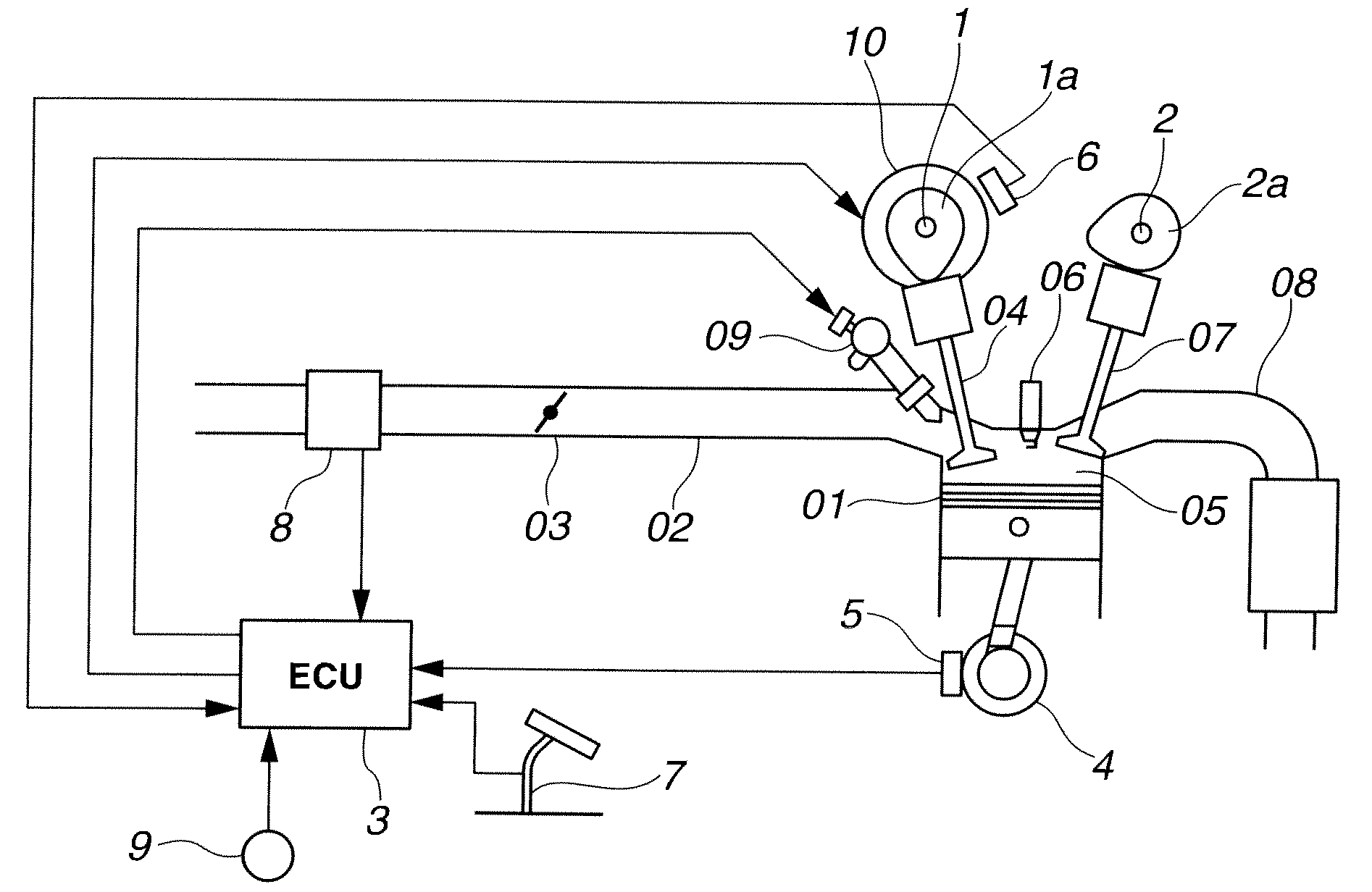
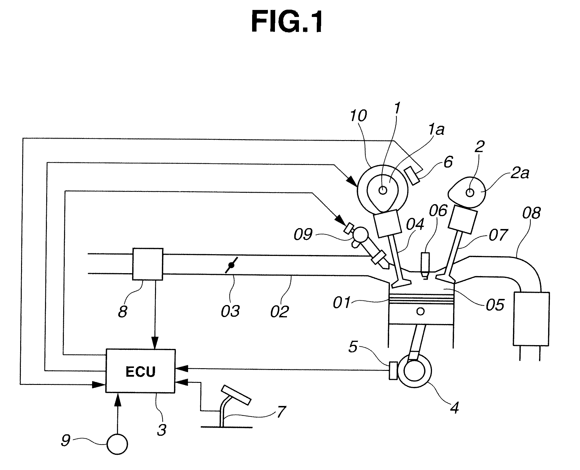
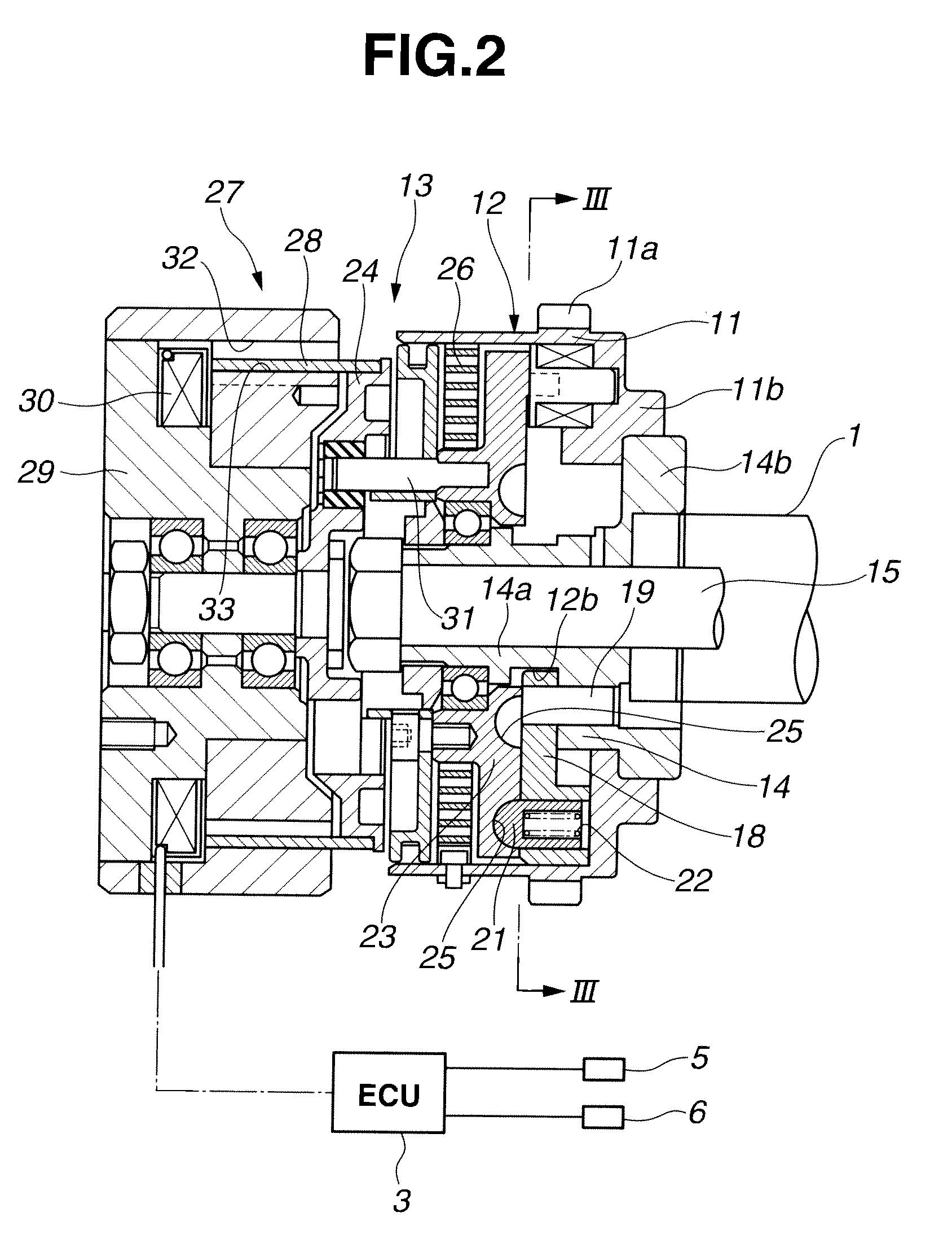
A valve timing control apparatus includes a phase varying mechanism arranged to vary a relative rotational phase of a cam shaft with respect to a crank shaft; a driving mechanism arranged to provide a driving force to the phase varying mechanism by energization; a control mechanism configured to control a current applied to the driving mechanism; and a phase angle sensing mechanism arranged to sense the relative rotational phase of the cam shaft with respect to the crank shaft, and to have a detection period longer than a control period of the control mechanism in accordance with an engine operating state. The control mechanism is configured to repeat increasing and decreasing of the current applied to the driving mechanism when the phase varying mechanism continuously varies the relative rotational phase of the cam shaft with respect to the crank shaft by a predetermined angle or more.

Description

BACKGROUND OF THE INVENTION[0001]This invention relates to a valve timing control apparatus configured to vary a relative rotational phase of a cam shaft with respect to a crank shaft of an internal combustion engine, and to vary a valve timing (opening and closing timing) of an intake valve or an exhaust valve.[0002]U.S. Pat. No. 7,441,524 (corresponding to Japanese Patent Application Publication No. 2005-299640) shows a valve timing control apparatus including a rotational phase sensing section configured to sense a relative rotational phase between a crank shaft and a cam shaft at an arbitrary timing. This valve timing control apparatus is controlled by the rotational phase sensed by the rotational phase sensing section.[0003]This valve timing control apparatus can sense the relative rotational phase even in a period shorter than a rotation period of the cam shaft. The feedback control of the valve timing control can be performed even at the low rotation speed so as to correspond...

Claims


Application Information

Patent Timeline
Patent Type & Authority Applications(United States)
IPC IPC(8): F01L1/34
CPCF01L1/344F01L2820/041F01L2800/00F01L2001/3522
Inventor KOKUBO, NAOKIKOBAYASHI, YOSHIYUKIWATANABE, MASAHIKOOOWADA, TAKAHUMI
Owner HITACHI LTD
Why Eureka
Eureka Blog
Learn More