
Linear motor

a linear vernier motor and motor technology, applied in the field of linear motors, can solve problems such as the deterioration of the controllability of linear vernier motors, and achieve the effect of reducing the detent for

Inactive Publication Date: 2016-11-10
INST OF NAT COLLEGES OF TECH JAPAN +1
View PDF4 Cites 1 Cited by
  • Summary
  • Abstract
  • Description
  • Claims
  • Application Information

AI Technical Summary

Benefits of technology

The present invention aims to provide a linear motor that can reduce detent force, which improves controllability. The technical effect of this invention is to improve the performance of linear motors by reducing detent force.

Problems solved by technology

As a result, controllability of the linear vernier motor deteriorates.

Method used


Image

  • Linear motor
  • Linear motor
  • Linear motor

Examples


Embodiment Construction

[0012]Hereinafter, an embodiment of the present invention will be described with reference to the accompanying figures.

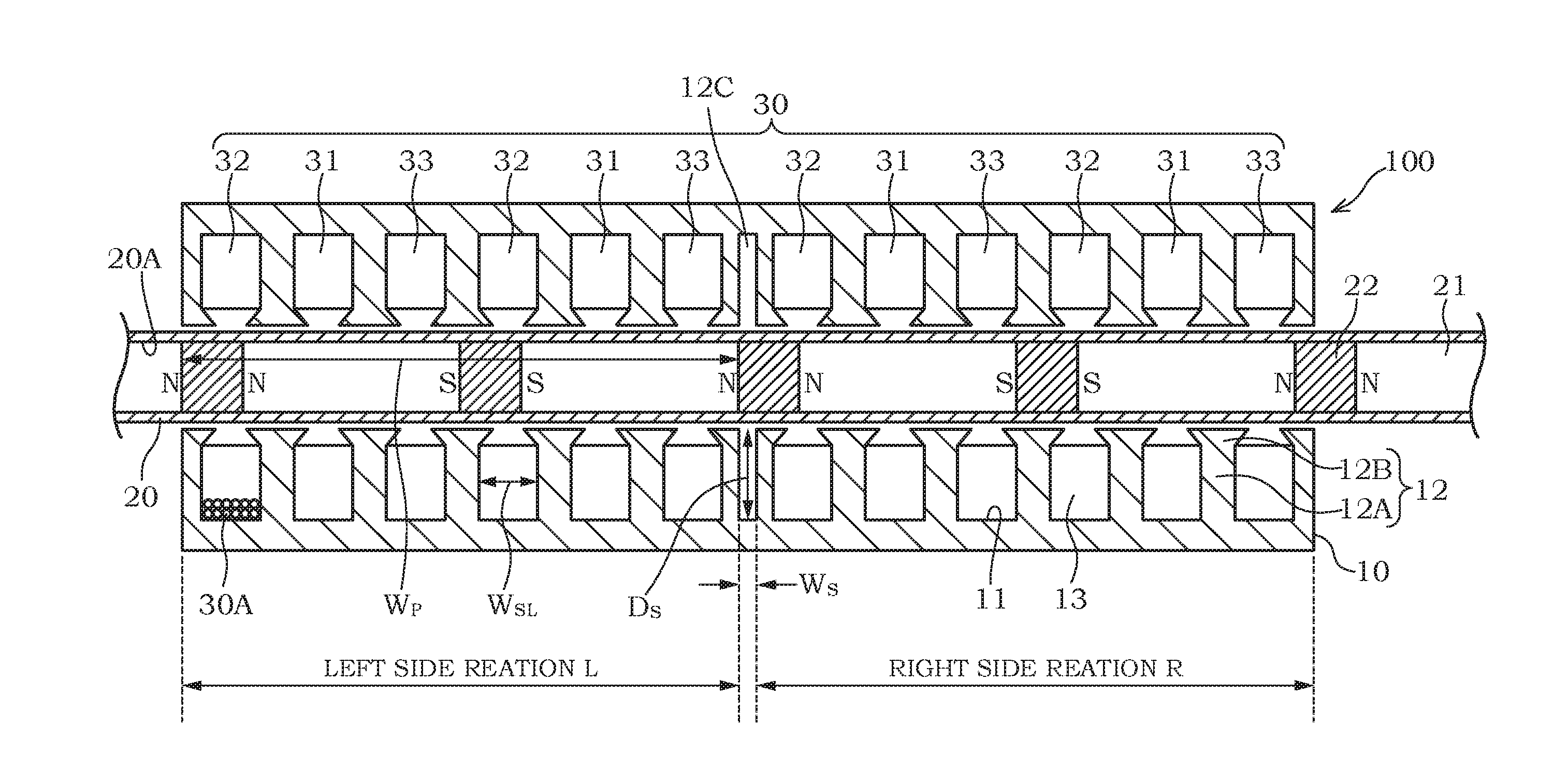
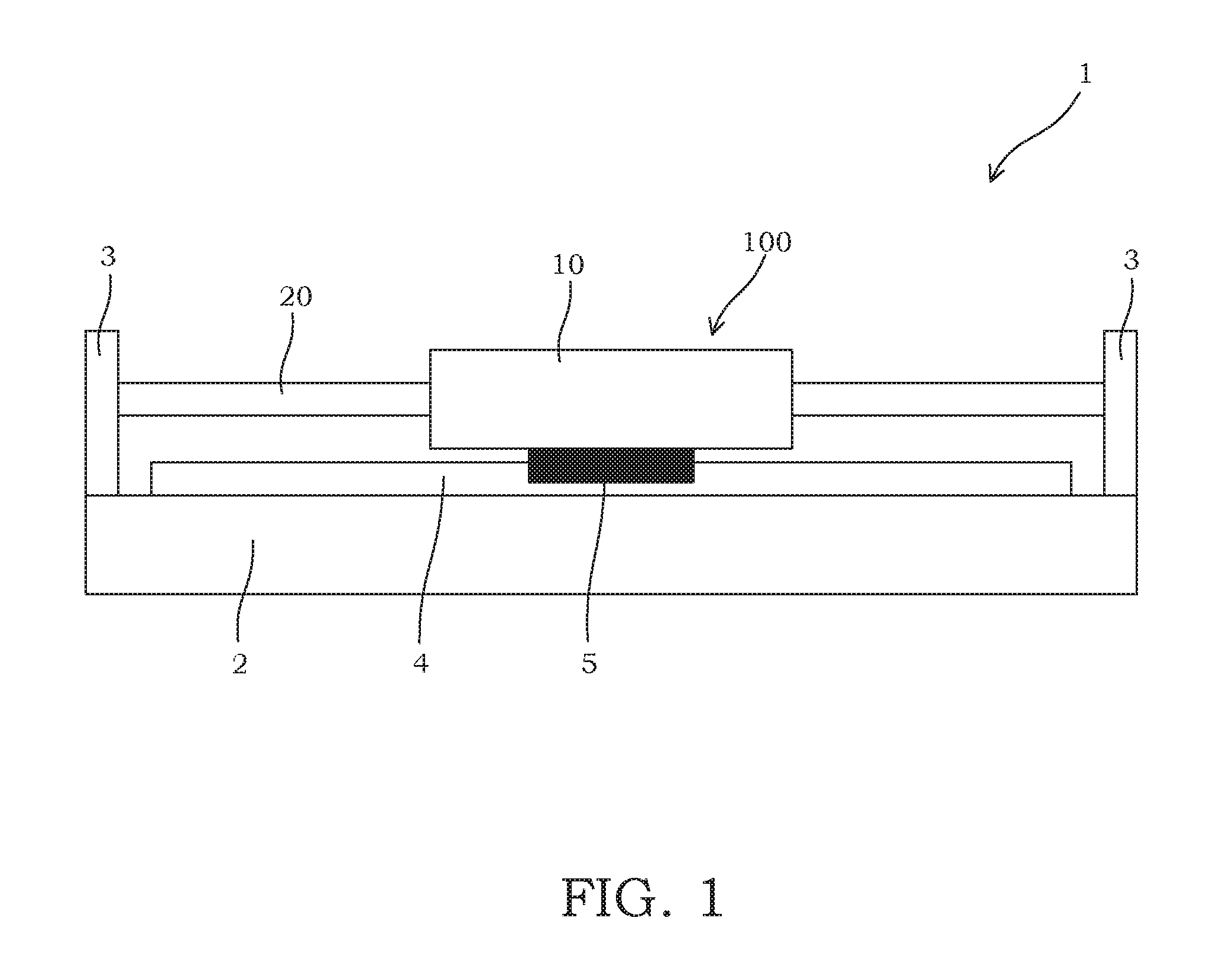
[0013]Referring to FIG. 1, an actuation system 1 including a linear motor 100 according to the present embodiment will be described.

[0014]The actuation system 1 includes: the linear motor 100, which includes a tubular yoke 10 and a rod 20; a mounting portion 2 on which the linear motor 100 is mounted; support portions 3 each standing on the mounting portion 2 to support respective ends of the rod 20, a rail 4 disposed on the mounting portion 2; and a carrier 5 that moves along the rail 4 while the yoke 10 is fixed thereto. When the linear motor 100 is driven, the yoke 10 moves along the rail 4 together with the carrier 5. In the actuation system 1, a driving subject such as a component is mounted on the yoke 10 so that the driving subject can be moved in a straight line.

[0015]It should be noted that although the actuation system 1 is configured as a driving actuatio...


PUM


Abstract

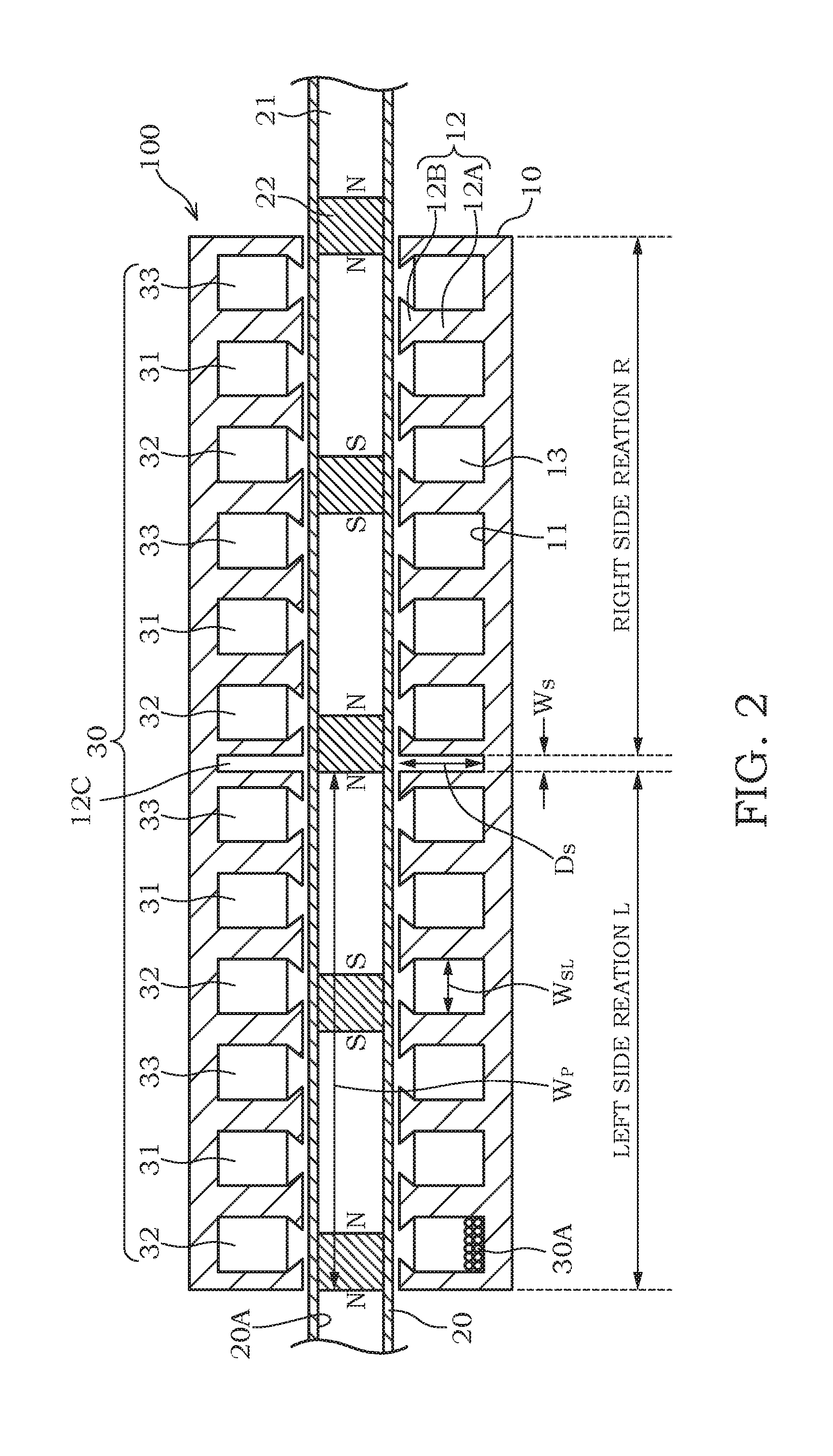
A linear motor includes: an annular yoke; a rod that penetrates the yoke in a yoke axis direction; a plurality of teeth disposed at equal intervals in the yoke axis direction so as to project from an inner peripheral surface of the yoke; slots respectively formed between adjacent teeth of the plurality of teeth, a plurality of coils respectively disposed in the slots, and permanent magnets arranged and held in the rod in the yoke axis direction. The yoke is configured so that the slots are disposed repeatedly by a reference number determined in accordance with the number of phases of an alternating current passed through the coils, and a width adjusting unit configured to adjust a tooth width is provided in an Nth tooth from a yoke end, the Nth tooth being determined by Equation (1).

Description

TECHNICAL FIELD[0001]The present invention relates to a linear motor.BACKGROUND ART[0002]JP2012-244688A discloses a linear vernier motor that displaces a tubular yoke and a rod relative to each other in an axial direction by attracting a permanent magnet disposed on an outer peripheral surface of the rod using a moving magnetic field generated around a coil disposed on an inner peripheral surface of the yoke.SUMMARY OF INVENTION[0003]It is known that in such a linear vernier motor, a detent force (a magnetic attraction force) is generated between the permanent magnet disposed on the rod and teeth formed in the yoke. A magnitude of the detent force varies periodically in accordance with relative positions of the rod and the yoke in the axial direction.[0004]A linear vernier motor illustrated in FIG. 4A of JP2012-244688A is configured so that a current passed through the coil is a three-phase alternating current, and the yoke is a twelve-slot yoke in which two sets of the reference nu...

Claims


Application Information

Patent Timeline
Patent Type & Authority Applications(United States)
IPC IPC(8): H02K1/16H02K41/03H02K3/28H02K1/34
CPCH02K1/165H02K3/28H02K41/031H02K1/34H02K29/03H02K2213/03
Inventor KANO, YOSHIAKISATO, KOUSUKETAKAHASHI, NORIYUKI
Owner INST OF NAT COLLEGES OF TECH JAPAN
Learn More