
Linear vernier motor

a vernier motor and linear technology, applied in the direction of dynamo-electric machines, electrical apparatus, propulsion systems, etc., can solve the problems of small difficult fixation of the permanent magnet to the mover, and detent force, so as to improve the driving force and reduce the detent force, the driving force to the own weight and volume of the motor can be made great, and the effect of improving the driving for

Inactive Publication Date: 2014-02-13
MITSUBISHI HEAVY IND LTD +1
View PDF5 Cites 7 Cited by
  • Summary
  • Abstract
  • Description
  • Claims
  • Application Information

AI Technical Summary

Benefits of technology

The present invention provides a linear vernier motor with improved driving force, making it possible to achieve greater weight and volume for the motor. Also, the detent force can be reduced and the motor can be easily assembled.

Problems solved by technology

In this structure, the fixation of the permanent magnet to the mover is difficult.
As a result, there is a problem that the driving force to the own weight and volume of the motor is small.
Also, there is a problem, which is common to the vernier motor, that detent force (the force which occurs periodically in the moving direction of the mover regardless of the existence or non-existence of the motor driving; the cogging force and the end effect) occurs.
However, in this method, the additional permanent magnets in the stator side do not contribute for the driving force at all, even though they have made the whole size, weight and cost greater.

Method used


Image

  • Linear vernier motor
  • Linear vernier motor
  • Linear vernier motor

Examples


first embodiment

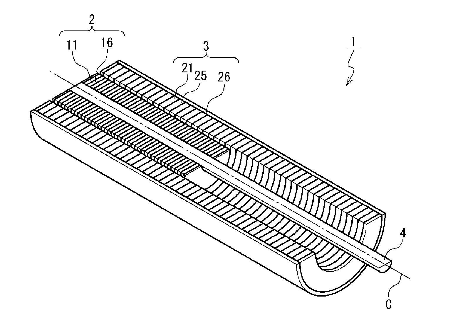
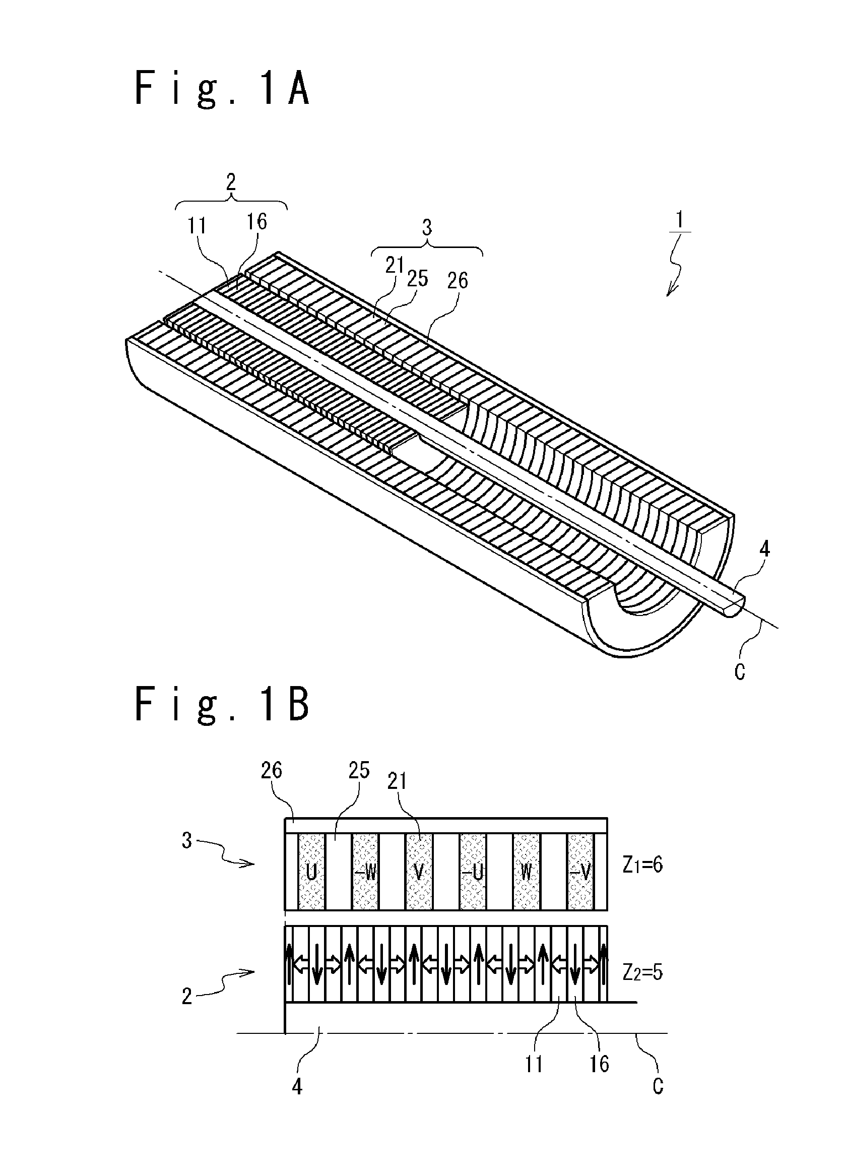
[0056]First, the structure of the linear vernier motor according to a first embodiment of the present invention will be described. FIG. 1A is a schematic diagram showing a configuration example of the linear vernier motor according to the first embodiment of the present invention. FIG. 1B is a schematic diagram showing a relation between stators and movers in FIG. 1A. However, FIG. 1A shows only a half of the linear vernier motor 1 for easy understanding. Also, FIG. 1B shows a periodic structure of a stator 3 and a mover 2 to be described later.

[0057]The linear vernier motor 1 is a linear-type vernier motor and is composed of the stator 3, the mover 2 and a fixation shaft member 4. The stator 3 has the shape of a circular cylinder which has an axis C as a central axis, and includes the mover 2 therein. The mover 2 has the shape of a circular cylinder which has the axis C as the central axis. The mover 2 is movable on the fixation shaft member 4 which passes through the inside of the...

second embodiment

[0092]Next, a structure of the linear vernier motor according to the second embodiment of the present invention will be described. The present embodiment is different from the first embodiment in the point that, mainly, the length of the mover 2 is changed in order to reduce the cogging force. As previously described, since the linear vernier motor is not a rotary motor, the length of the mover can be freely changed and the flexibility of the design is high even at this point. In the present embodiment, the point different from the first embodiment will be mainly described.

[0093]The result of the consideration that the inventor carried out about the relation between the detent force and the number of the permanent magnets of the mover will be described. FIG. 7 is a schematic diagram showing the structure of the mover and position relation between the mover and the stator. The stator 3 is the same as the case (FIG. 1A and FIG. 1B) of the first embodiment. It is supposed that the refe...


PUM


Abstract

A linear vernier motor includes a stator and a mover. The stator extends in a first direction. The mover extends in the first direction and a pole interval is different from that of the stator. At least one of the stator and the mover includes: a plurality of permanent magnets arranged in the first direction and a plurality of yokes arranged in the first direction. Each of the plurality of yokes is arranged between adjacent permanent magnets. The plurality of permanent magnets is magnetized to the first direction and magnetization orientations of adjacent permanent magnets are opposite to each other.

Description

TECHNICAL FIELD[0001]The present invention relates to a linear vernier motor.BACKGROUND ART[0002]A vernier-type linear motor has been proposed, in which a mover period and a stator period are different from each other to improve driving force (torque) of the linear motor. For example, a non-patent literature 1 discloses a PM-type linear vernier motor. This non-patent literature 1 proposes a technique which reduces pulsing force caused by cogging force and end effect occurring in the linear vernier motor.[0003]Also, a patent literature 1 discloses an electric power steering apparatus using the linear vernier motor. This electric power steering apparatus includes: a pinion which is provided at a tip of a steering shaft and rotates with the steering shaft; a rack bar which engages with the pinion and makes a steering angle change by transforming rotary motion of the steering shaft into rectilinear motion of a longitudinal direction; a housing which houses the pinion and the rack bar; a...

Claims


Application Information

Patent Timeline
Patent Type & Authority Applications(United States)
IPC IPC(8): H02K41/02
CPCH02K41/02H02K41/031H02K2213/03
Inventor HIURA, RYOTAHIRATA, KATSUHIROISHIGURO, HIROSHINAKATA, YOSHIHIRO
Owner MITSUBISHI HEAVY IND LTD
Learn More