Rotating electric machine control system
a control system and electric machine technology, applied in the direction of electric commutators, propulsion by batteries/cells, transportation and packaging, etc., can solve the problems of increasing manufacturing costs, deteriorating and difficulty in time-synchronization (a) of current/voltage detector detection values with (b) detection values from rotation detectors, so as to prevent deterioration of controllability of voltage converters
- Summary
- Abstract
- Description
- Claims
- Application Information
AI Technical Summary
Benefits of technology
Problems solved by technology
Method used
Image
Examples
first embodiment
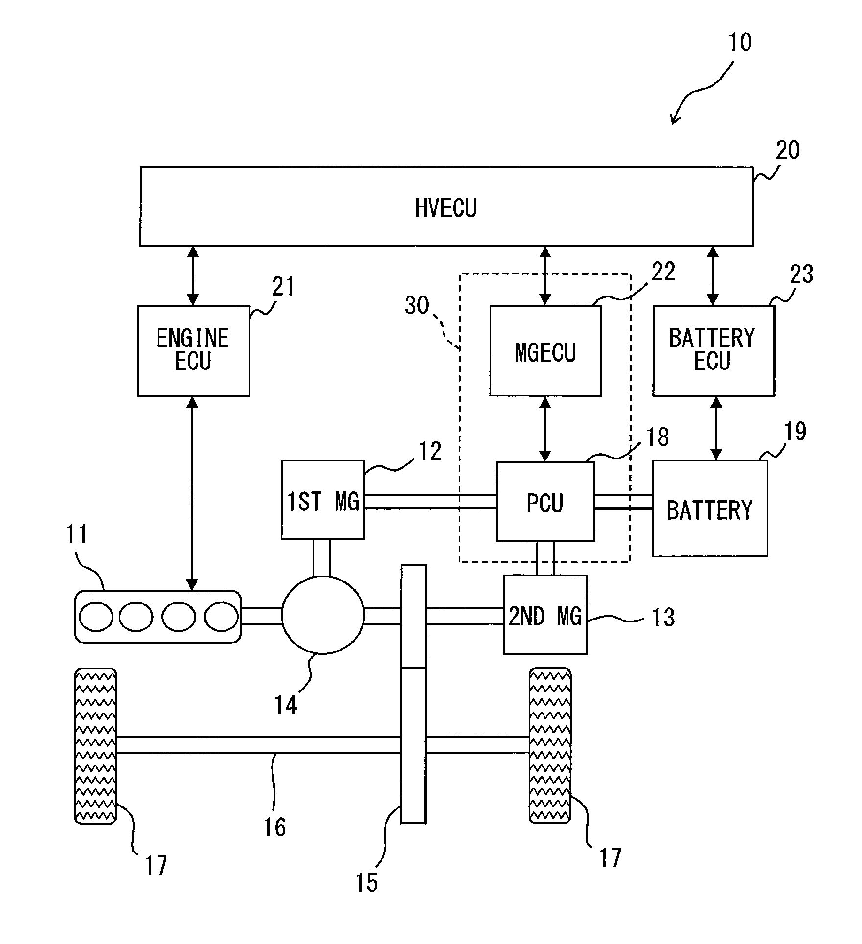
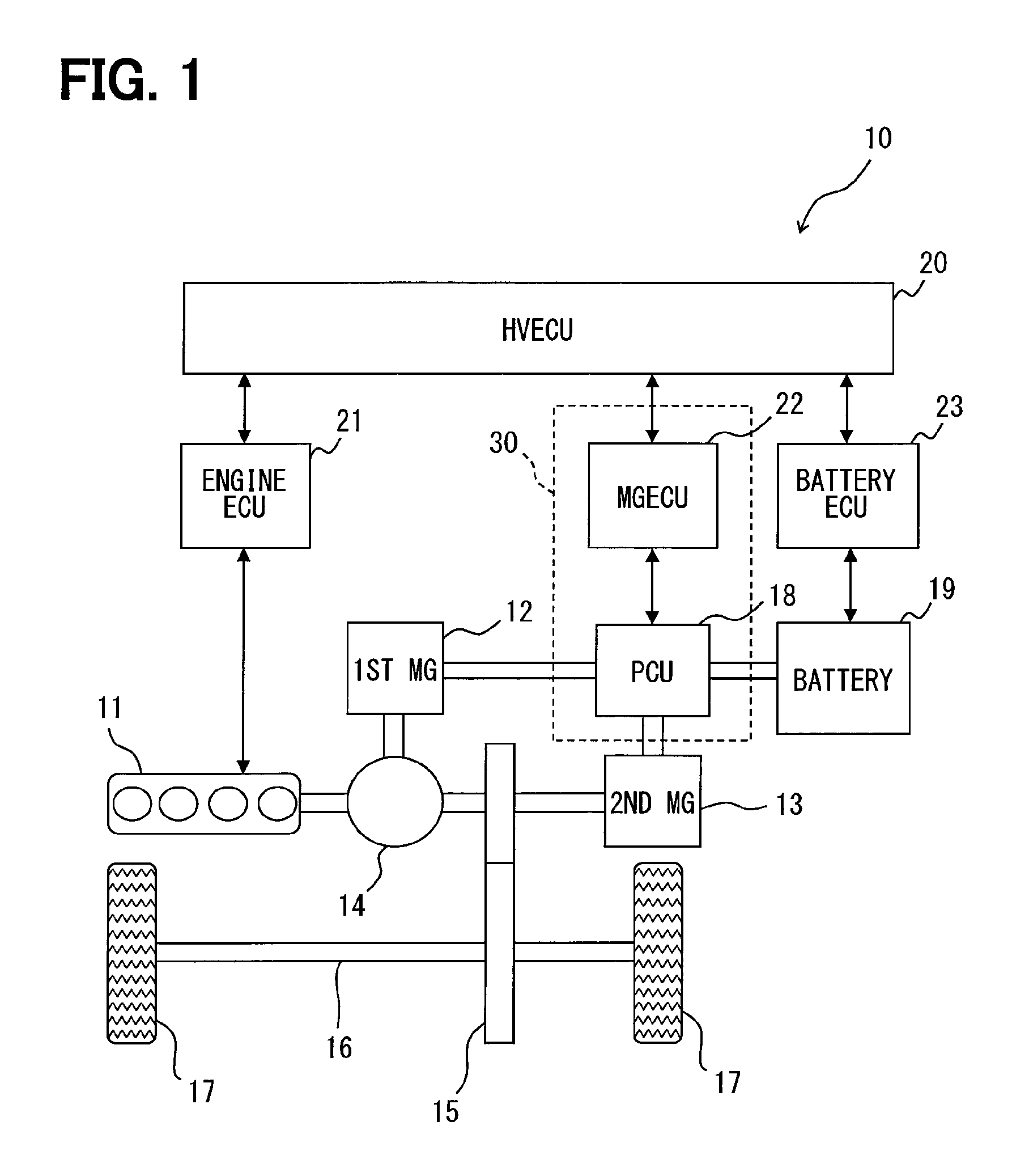
[0033]In the first embodiment, an application of an MG control system to a split-type hybrid vehicle is described.
[0034]First, an outline configuration of a hybrid vehicle is described based on FIG. 1
[0035]As shown in FIG. 1, a hybrid vehicle 10 is provided with an engine 11 which is an internal-combustion engine, a first motor-generator 12, and a second motor-generator 13. The motor-generator may also be designated as the MG, which means that the MG 12 or the first MG 12 represents the first motor-generator 12. Further, the MG 13 or the second MG 13 represents the second motor-generator 13. These MGs 12 and 13 are equivalent to a rotating electric machine in the claims.
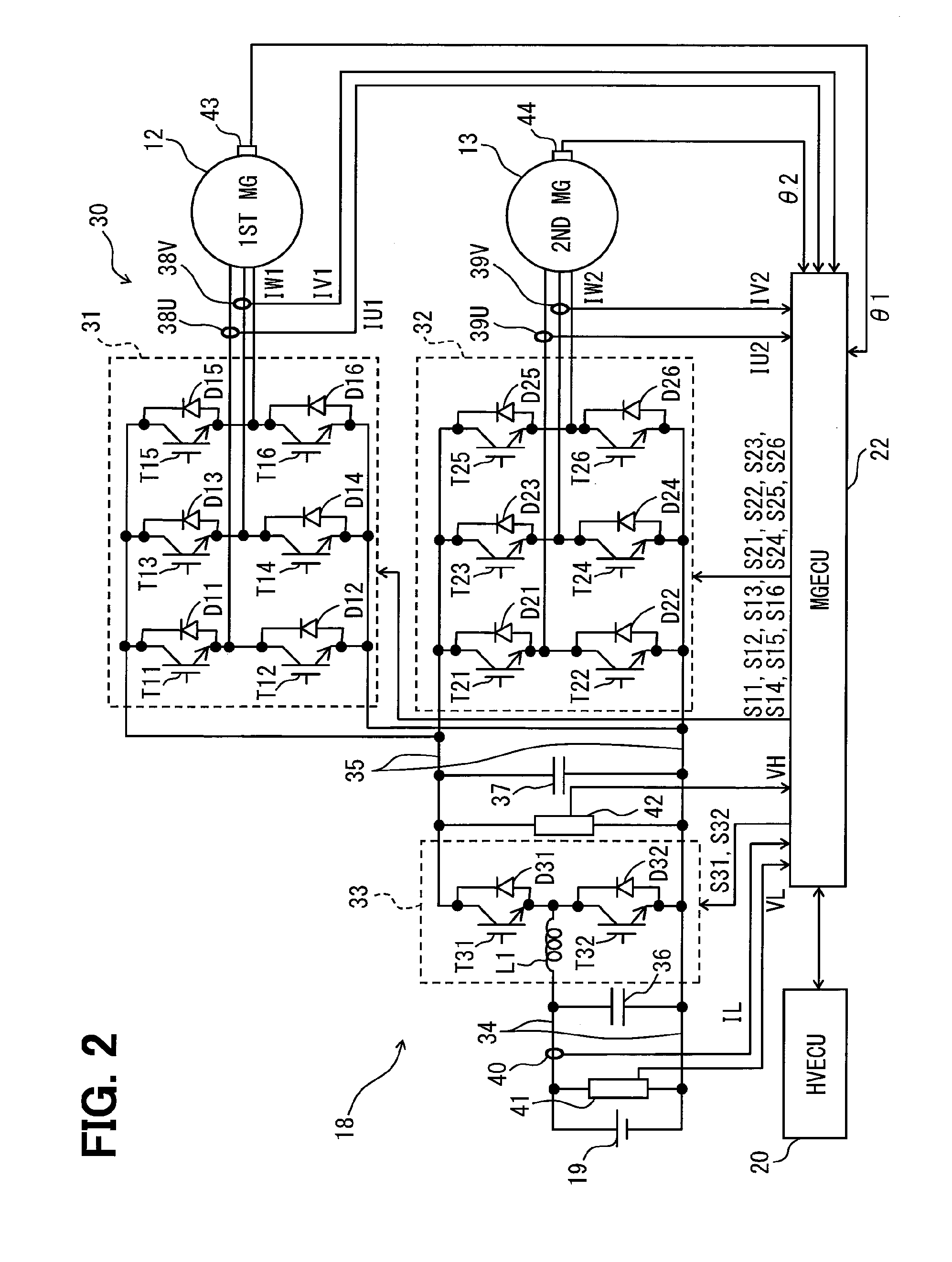
[0036]The MGs 12 and 13 are respectively constituted as a synchronous generator-motor, which has the rotator having a permanent magnet attached thereon, and the stator having three phase windings wound thereon. The first MG 12 generates electricity by receiving a driving force from outside thereof, and serves as a st...
second embodiment
[0145]In the present embodiment, the common part with the preceding embodiment will not be repeated in the description, and only the difference therefrom is described for the MG control system 30.
[0146]According to the present embodiment, as shown in FIG. 10, the PCU 18 includes, as a first timer, a first real-time clock 51 (i.e., a first RTC 51, hereafter) and the MGECU 22 includes, as a second timer, a second real-time clock 52 (i.e., a second RTC 52, hereafter). Each of the two real-time clocks 51, 52 always receives a power supply, for measuring time.
[0147]The time correction process for correcting the relative time difference between the real-time clocks 51, 52 is described with reference to flowcharts in FIGS. 11 and 12.
[0148]FIG. 11 illustrates a process in the time corrector 49. When the ignition signal IG shows a high-level signal, indicating an ON state, the power supply for the MGECU 22 is turned ON. After a preset stabilization time from such turning ON of the MGECU 22, ...
PUM
 Abstract
Description
Claims
Application Information
 - R&D
- Intellectual Property
- Life Sciences
- Materials
- Tech Scout
- Unparalleled Data Quality
- Higher Quality Content
- 60% Fewer Hallucinations
Browse by: Latest US Patents, China's latest patents, Technical Efficacy Thesaurus, Application Domain, Technology Topic, Popular Technical Reports.
© 2025 PatSnap. All rights reserved.Legal|Privacy policy|Modern Slavery Act Transparency Statement|Sitemap|About US| Contact US: help@patsnap.com


