Rotating electric machine control system

a control system and electric machine technology, applied in the direction of dynamo-electric converter control, motor/generator/converter stopper, electronic commutator, etc., can solve the problems of increasing manufacturing costs, deteriorating and difficulty in time-synchronization (a) of current/voltage detector detection values with (b) detection values from rotation detectors, so as to prevent deterioration of controllability of voltage converters

Active Publication Date: 2015-11-19
DENSO CORP
View PDF9 Cites 0 Cited by
  • Summary
  • Abstract
  • Description
  • Claims
  • Application Information

AI Technical Summary

Benefits of technology

[0017]In such manner, synchronization between (i) the timing of obtaining the rotation position, which is detected by the rotation detector, by the operation unit and (ii) the timing of obtaining the detection values (i.e., detected current values or detected voltage values), which are detected by the current / voltage detectors, by the communicator is achieved, for the generation of the communication frame. That is, the operation unit can perform the preset operation based on the rotation position, detected current values, and detected voltage values that are obtained at the same time (i.e., simultaneously) from respective detectors, thereby preventing a deterioration of the controllability of the voltage converter.

Problems solved by technology

The increase of the number of communication lines means an increase of the manufacturing cost.
However, the delay of communication caused by a transmission via the multiplex communication line will make it difficult to time-synchronize (a) the detection values from the current / voltage detectors with (b) the detection value from the rotation detector.
In other words, the controllability of the voltage converter may be deteriorated.

Method used


Image

  • Rotating electric machine control system
  • Rotating electric machine control system
  • Rotating electric machine control system

Examples


first embodiment

[0033]In the first embodiment, an application of an MG control system to a split-type hybrid vehicle is described.

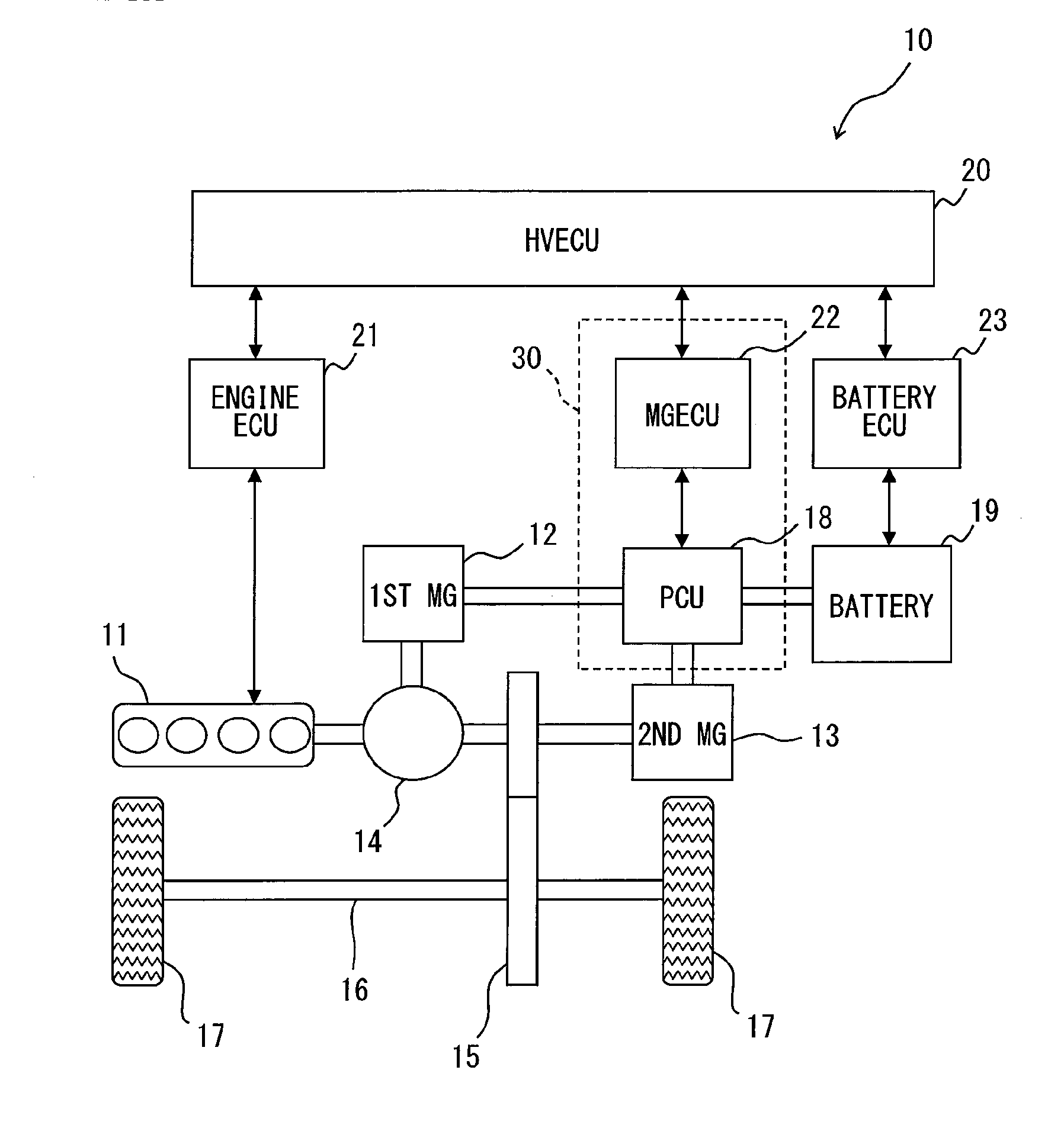
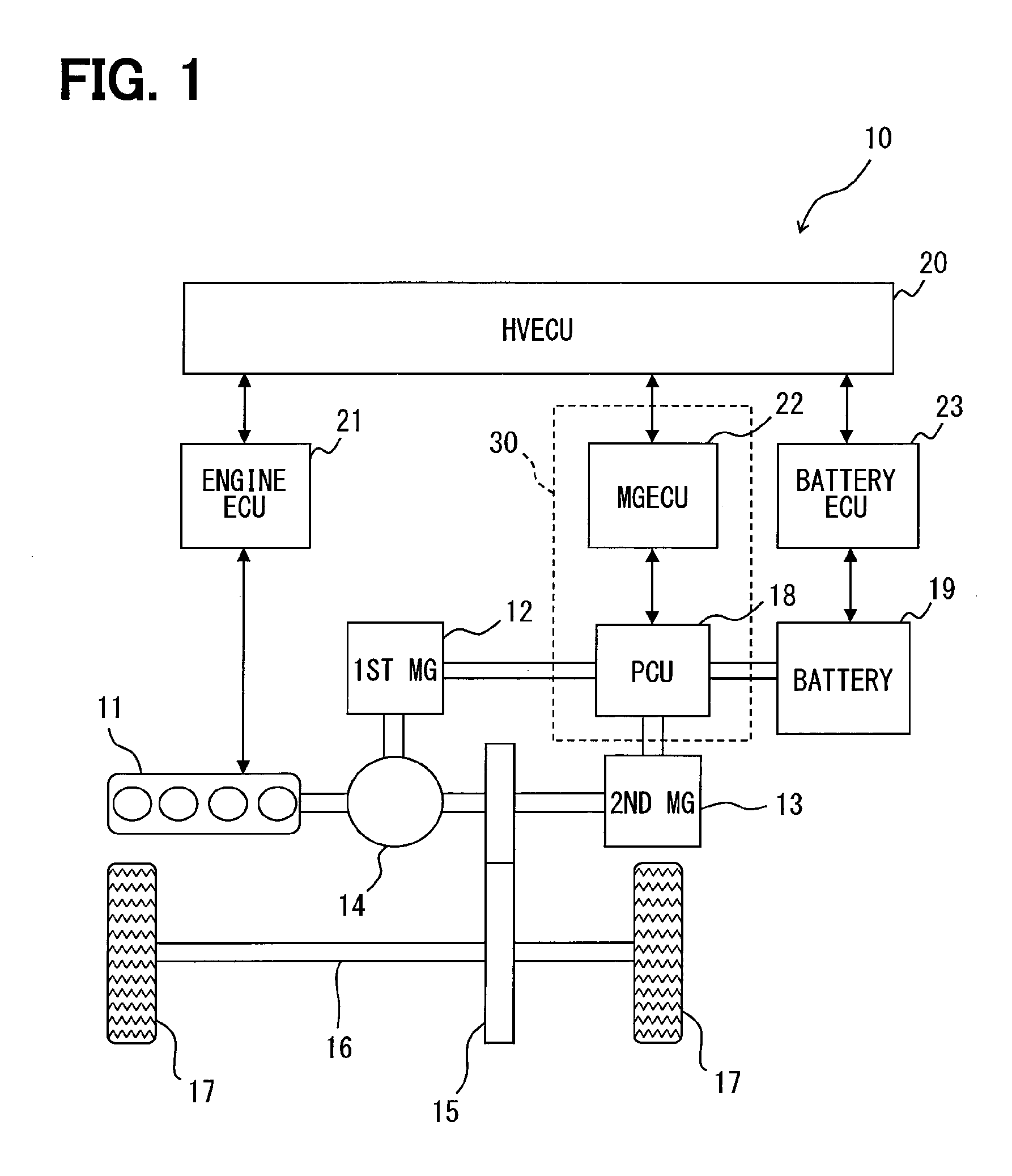
[0034]First, an outline configuration of a hybrid vehicle is described based on FIG. 1

[0035]As shown in FIG. 1, a hybrid vehicle 10 is provided with an engine 11 which is an internal-combustion engine, a first motor-generator 12, and a second motor-generator 13. The motor-generator may also be designated as the MG, which means that the MG 12 or the first MG 12 represents the first motor-generator 12. Further, the MG 13 or the second MG 13 represents the second motor-generator 13. These MGs 12 and 13 are equivalent to a rotating electric machine in the claims.

[0036]The MGs 12 and 13 are respectively constituted as a synchronous generator-motor, which has the rotator having a permanent magnet attached thereon, and the stator having three phase windings wound thereon. The first MG 12 generates electricity by receiving a driving force from outside thereof, and serves as a st...

second embodiment

[0145]In the present embodiment, the common part with the preceding embodiment will not be repeated in the description, and only the difference therefrom is described for the MG control system 30.

[0146]According to the present embodiment, as shown in FIG. 10, the PCU 18 includes, as a first timer, a first real-time clock 51 (i.e., a first RTC 51, hereafter) and the MGECU 22 includes, as a second timer, a second real-time clock 52 (i.e., a second RTC 52, hereafter). Each of the two real-time clocks 51, 52 always receives a power supply, for measuring time.

[0147]The time correction process for correcting the relative time difference between the real-time clocks 51, 52 is described with reference to flowcharts in FIGS. 11 and 12.

[0148]FIG. 11 illustrates a process in the time corrector 49. When the ignition signal IG shows a high-level signal, indicating an ON state, the power supply for the MGECU 22 is turned ON. After a preset stabilization time from such turning ON of the MGECU 22, ...


PUM


Abstract

A rotating electric machine control system having a power control unit equipped with a voltage converter and a controller. The controller is equipped with an operation unit having a time corrector for obtaining time from first and second timers with reference to an ignition signal and correcting a relative time difference between the timers. The operation unit obtains electric angles at a preset cycle after correcting time. A communicator obtains electric currents and voltages when obtaining the electric angles for generating a communication frame, and outputs the communication frame to the operation unit via the multiplex communication line. The operation unit simultaneously performs an operation for controlling an inverter and a booster converter based on the obtained electric currents, the voltages, and the electric angles, for reducing the number of communication lines between the power control unit and the controller without compromising controllability of the voltage converter.

Description

CROSS REFERENCE TO RELATED APPLICATION[0001]The present application is based on and claims the benefit of priority of Japanese Patent Application No. 2014-100671, filed on May 14, 2014, the disclosure of which is incorporated herein by reference.TECHNICAL FIELD[0002]The present disclosure generally relates to a rotating electric machine control system for controlling rotating electric machines in a vehicle.BACKGROUND INFORMATION[0003]Conventionally, within the art of rotating electric machines, a rotating electric machine control system used in a vehicle is known, with which at least one of rotating electric machines in a vehicle for providing a power for a travel of the vehicle is controlled.[0004]For example, a patent document 1 (i.e., Japanese Patent No. JP-A-2013-1185) discloses a rotating electric machine control system having a voltage converter for converting a direct current voltage of a direct current power source and outputting a converted three-phase alternating current t...

Claims


Application Information

Patent Timeline
Patent Type & Authority Applications(United States)
IPC IPC(8): H02P6/14B60L11/00
CPCB60L11/00H02P6/142H02P6/15H02P5/74H02P6/16B60L2210/40B60L2240/80B60L2260/10Y02T90/16B60L50/00B60L50/51Y02T10/64Y02T10/72Y02T10/70H04L1/00
Inventor SAKAI, NAOTO
Owner DENSO CORP
Why Eureka
Try Eureka