Elevated bench

A technology for lifting worktables and lifting tubes, which is applied in the direction of workbenches and manufacturing tools, which can solve the problems of low safety of workbenches, indiscriminate worktable surfaces, and injuries to operators' hands, so as to achieve easy classification and placement, and work efficiency High, the effect of preventing accidental injury

Inactive Publication Date: 2009-04-29
谢翠斌
View PDF1 Cites 8 Cited by
  • Summary
  • Abstract
  • Description
  • Claims
  • Application Information

AI Technical Summary

Problems solved by technology

Patent No. 200420019333.0 discloses a lifting workbench. Its disadvantages are: the worktable is not divided into grids, and when placing maintenance equipment, it is easy to place small nuts, gaskets, etc. with large parts or maintenance tools in confusion, which brings many problems to maintenance. It is inconvenient; moreover, it is easy to pull the lifting tube out of the column when the workbench is raised. When the workbench is lowered, because there is no preventive device, the lifter will quickly drop into the column, which is easy to injure the operator's hand and cause accidents. Low security at the workbench

Method used


Image

  • Elevated bench
  • Elevated bench

Examples


Embodiment Construction

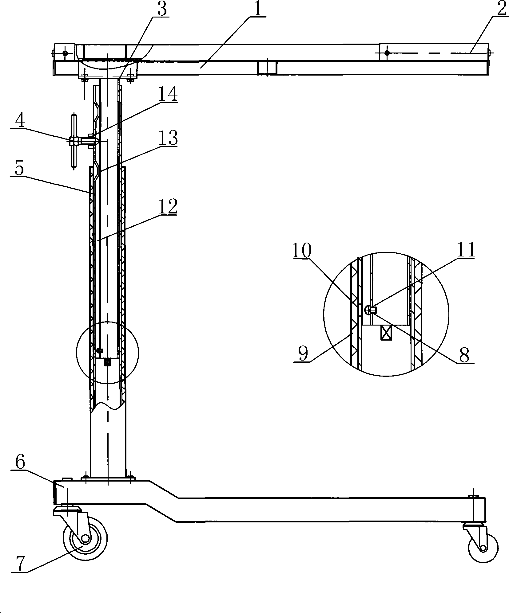
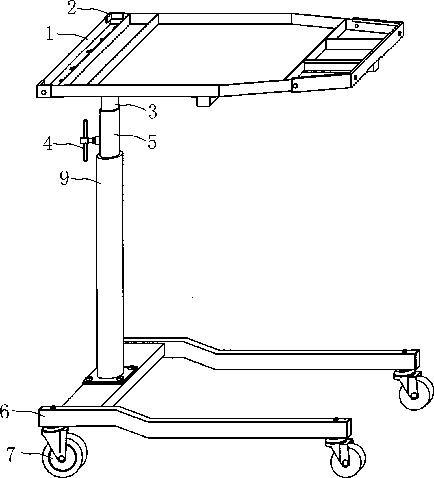
[0012] The present invention will be further described below in conjunction with accompanying drawing.

[0013] figure 1 , 2 An elevating workbench shown in , includes a working plate 1, an underframe 6, a column 5, and a lifting tube 3. The column 5 is set on the beam of the underframe 6, and the lifting tube 3 is set on one side of the bottom surface of the working plate 1. The pipe 3 is set in the column 5, and the bottom frame 6 is provided with universal wheels 7. The outer wall of the upper part of the column 5 is provided with two grooves 13, and a nut 14 is welded between the two grooves. The "T" type screw 4 passes through the nut 14 to press the lifting tube 3, and the outer wall of the lifting tube 3 is provided with a guide groove 12 from top to bottom. The bottom of the guide groove 12 is provided with a threaded hole 11 corresponding to the through hole 10, the bottom of the column 5 is provided with a through hole 10, a stop nut 8 passes through the through ho...


PUM


Abstract

The invention relates to a lifting working platform, comprising a working plate, a bottom frame, an upright post and a lifting tube; wherein, the lifting tube is arranged at the lower end of the working plate; the upright post is arranged on the bottom frame; the lifting tube is sleeved into the upright post; the bottom frame is provided with a universal wheel; two flutes are vertically positioned on the upper part of the outer wall of the upright post and a through hole is arranged at the lower part of the upright post; a guide groove is positioned on the outer wall of the lifting tube from top to bottom; a screw thread hole which is corresponding to the through hole is arranged at the lower part of the guide groove; and a stop nut goes through the through hole and is locked to the screw thread hole. The working table of the invention is safe and stable in sharp rising and falling, fixed and simple in operation, and convenient for the classification placement of tools, can be inserted deep into bottoms of cars and is suitable for a plurality of occasions.

Description

technical field [0001] The invention relates to an elevating workbench, in particular to an elevating workbench suitable for automobile maintenance. Background technique [0002] In mechanical maintenance, especially when repairing cars, it is usually used with a workbench to place tools, parts and other maintenance equipment. Patent No. 200420019333.0 discloses a lifting workbench. Its disadvantages are: the worktable is not divided into grids, and when placing maintenance equipment, it is easy to place small nuts, gaskets, etc. with large parts or maintenance tools in confusion, which brings many problems to maintenance. It is inconvenient; moreover, it is easy to pull the lifting tube out of the column when the workbench is raised. When the workbench is lowered, because there is no preventive device, the lifter will quickly drop into the column, which is easy to injure the operator's hand and cause accidents. Workbench security is low. Contents of the invention [000...

Claims


Application Information

Patent Timeline
Patent Type & Authority Applications(China)
IPC IPC(8): B25H1/16
Inventor 谢翠斌
Owner 谢翠斌
Why Eureka
Try Eureka