Quick-releasing mechanism

A release mechanism and fast technology, which is applied in the field of special equipment for emergency rescue supplies, can solve the problems of increase, delivery volume limitation, endangering personnel safety, etc., and achieve the effect of simple overall structure

Active Publication Date: 2009-04-29
常熟华东汽车有限公司
View PDF0 Cites 10 Cited by
  • Summary
  • Abstract
  • Description
  • Claims
  • Application Information

AI Technical Summary

Problems solved by technology

The shortcomings of the electromagnetic release mechanism for delivering materials are: the amount of delivery is limited each time. The limitation referred to here means that the weight of the material cannot be greater than the magnetic force that the electromagnet can hold.
In order to increase the amount of delivery each time, the electromagnetic intensity of the electromagnetic mechanism must be increased, that is, the magnetic strength of the electromagnet; since the electromagnetic release mechanism needs to rely on a power supply, it will be restricted by conditions; the safety cannot be fully guaranteed. For example, once the electromagnetic mechanism loses power halfway, it will cause material damage and even endanger the safety of the rescued personnel.
[0005] Perhaps based on the many deficiencies of the above-mentioned various delivery methods, at present, more materials are still delivered by the original throwing method and the use of hooks. The hook delivery method is safe and accurate, but when the After the material reaches the target, it is necessary to use the personnel at the target place to release the hook from the material, but in some states, it is often impossible to do this
For example, when a helicopter, especially a ship, puts equipment such as a lifeboat into the sea, additional personnel are usually dispatched to arrive at the lifeboat or take off the hook with the lifeboat when it enters the sea, which is not conducive to ensuring safety.

Method used


Image

  • Quick-releasing mechanism
  • Quick-releasing mechanism

Examples


Embodiment

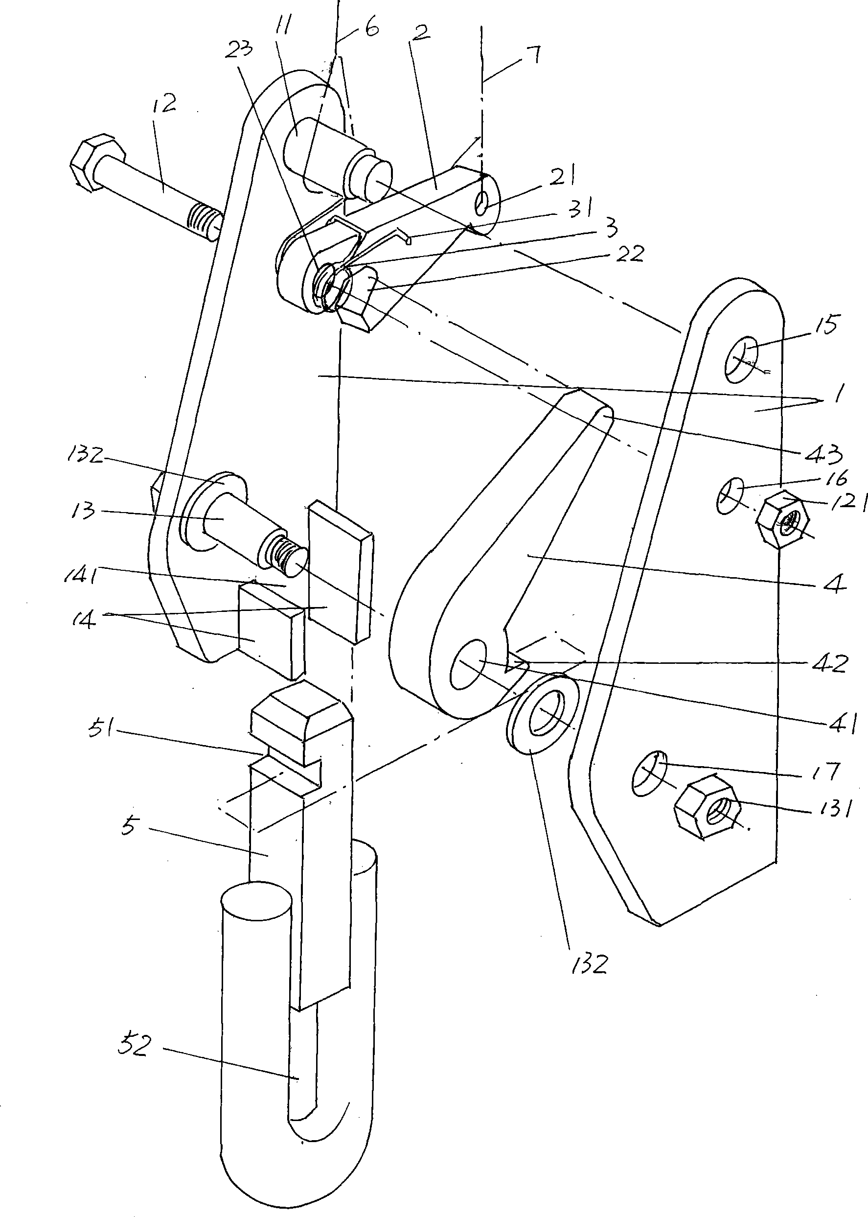
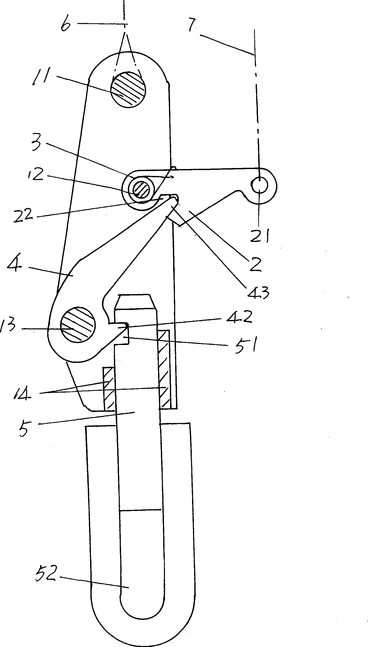
[0022] please see figure 1 , a pair of hook seat plates 1 that are identical in shape and structure to each other and tend to be pipa-shaped are provided. Of course, the shape of the hook seat 1 can have other variations, and the pipa-shaped shape mentioned by the applicant is only as a preferred shape. A pair of hook seat plates 1 are arranged face to face, and a reasonable distance is reserved between each other. The reasonable distance mentioned here refers to at least the maximum thickness of the hook foot 2, the limit card 4 and the release hook 5, so that the hook The pin 2, the limit card 4 and the release hook 5 can move freely between a pair of hook seat plates 1, so as to avoid the stagnation phenomenon. On a pair of hook seat plates 1 and at positions corresponding to each other, first, second, and third shaft holes 15, 16, 17 are sequentially opened from top to bottom, wherein: a pair of first shaft holes 15 are provided ( connection) sling shaft 11; a pair of se...


PUM


Abstract

A quick-releasing mechanism belongs to the technical field of special apparatuses used for emergency relief materials delivery and comprises a couple of hook base plates mutually connected through a sling shaft, a clamp-pin hook shaft and a limit clamp shaft; a couple of guide plates formed with a releasing hook cavity are arranged on any one of the couple of hook base plates; a clamp-pin hook is adopted and one end of the clamp-pin hook is sleeved onto the clamp-pin hook shaft and the other end is free; a torsion spring is sleeved on the clamp-pin hook shaft and the middle part of the torsion spring is forced onto the clamp-pin hook and a couple of torsion spring feet are supported by the couple of hook base plates; a limit clamp is adopted and one end of the limit clamp is sleeved onto the limit clamp shaft and the other end corresponds to and is connected with the clamp-pin hook; and a releasing hook is arranged in the releasing hook cavity formed between the couple of guide plates and is connected with the limit clamp. The quick-releasing mechanism has the advantages that the safety can be guaranteed; the mechanism can be applied to both water and land areas so as to break the environment limit; and the integral structure is simple.

Description

technical field [0001] The invention belongs to the technical field of special equipment for putting in emergency rescue materials, and in particular relates to a quick release mechanism. Background technique [0002] There are generally but not limited to two rescue situations in marine rescue. One is that aircrafts drop various materials to the sea or the rescued target; the other is that search and rescue ships including warships deliver rescue materials such as lifeboats and life buoys , life jackets and food and medicine and so on. [0003] Ground rescue mainly relies on airplanes to drop corresponding materials to the destination, which can be understood through a large number of reports on the rescue process of the Wenchuan earthquake. [0004] One of the delivery methods of rescue materials in the prior art is to throw them directly to the target location by throwing them. The disadvantage of this method is that the arrival location of the materials is not accurate,...

Claims


Application Information

Patent Timeline
Patent Type & Authority Applications(China)
IPC IPC(8): B63C9/01B64D1/00
Inventor 刘懋功马知才张淳王健潘志锋何兴华刘金山钱鹏
Owner 常熟华东汽车有限公司
Why Eureka
Try Eureka