Switching device

A switching device and signal receiving end technology, applied in the direction of selection device, logic circuit connection/interface layout, line transmission components, etc., can solve the problems of time and cost waste, cumbersome implementation, and signal transmission failure of the switching device.

Inactive Publication Date: 2009-04-29
HONG FU JIN PRECISION IND (SHENZHEN) CO LTD +1
View PDF0 Cites 3 Cited by
  • Summary
  • Abstract
  • Description
  • Claims
  • Application Information

AI Technical Summary

Problems solved by technology

[0002] At present, the method of connecting a switching device between two pieces of hardware is often used for signal transmission between the two pieces of hardware. output terminal, the input terminal of the adapter device is connected to the signal output terminal of a hardware, and the output terminal of the adapter device is connected to the signal input terminal of another hardware, so that the signal of the signal output terminal of the first hardware can be It is transmitted to the signal input of the other hardware, but the data line on the conversion device is often short-circuited or disconnected due to pollution with oil, debris, etc., or other reasons, causing some signal transmission failures on the conversion device , in view of this situation, the traditional processing method is to use a spare data line to manually replace the data line with signal short circuit or open circuit on the adapter device, or directly replace a new adapter device, although these two methods can solve the problem. The problem of short circuit or open circuit of the data line of the transfer device, but the timeliness is poor, and the implementation is cumbersome, resulting in waste of time and cost

Method used


Image

  • Switching device

Examples


Embodiment Construction

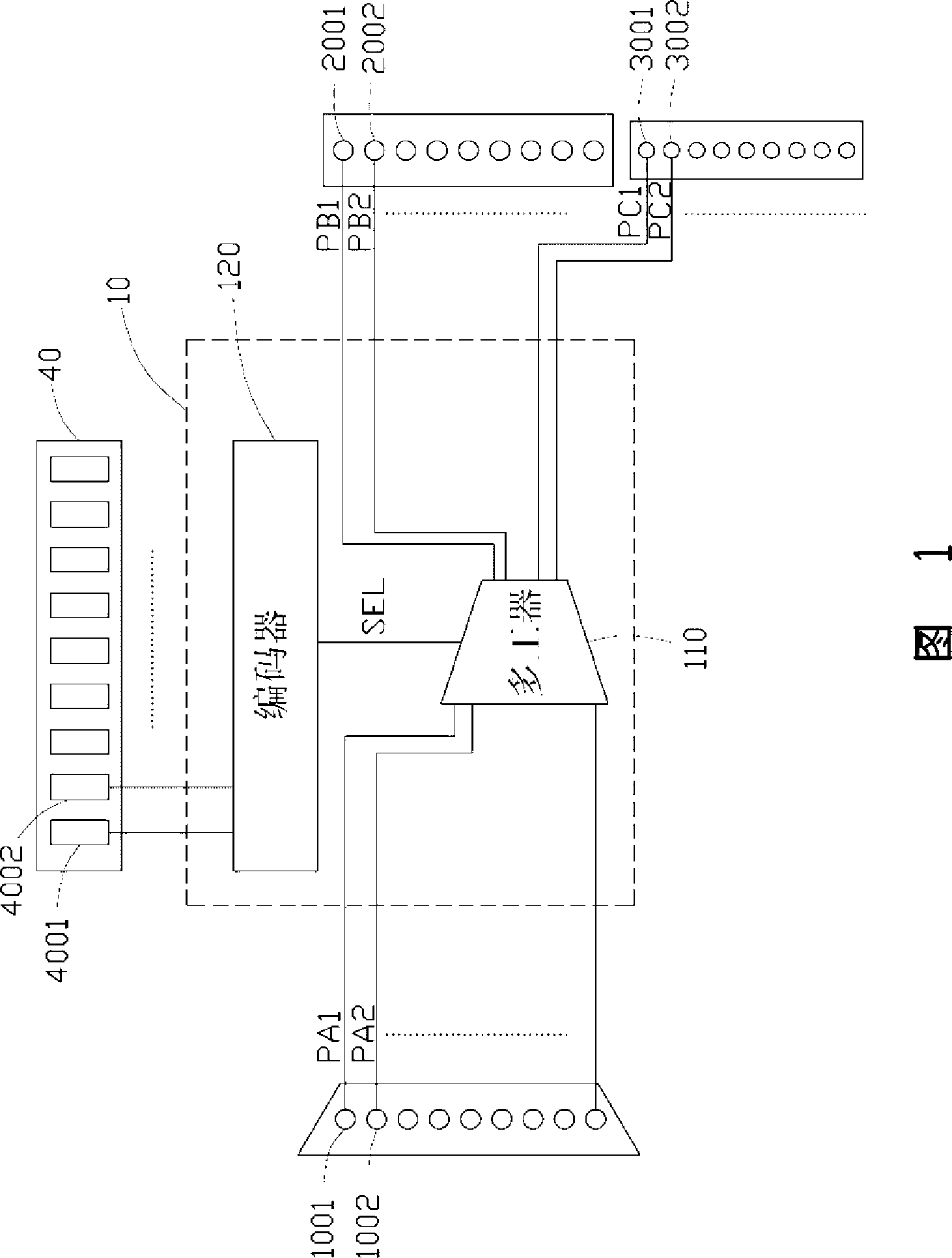
[0008] Referring to Fig. 1, the preferred embodiment of the switching device of the present invention includes a programmable logic device 10, several signal receiving terminals 1001, 1002..., several signal transmitting terminals corresponding to the signal receiving terminals 1001, 1002... 2001, 2002..., a number of spare ends 3001, 3002... corresponding to the signal transmitting ends 2001, 2002... and a jumper setting device 40, the signal receiving ends 1001, 1002... are used to connect a first hardware (not shown in the figure) signal output end, the signal transmission end 2001, 2002 ... and the spare end 3001, 3002 ... are used to connect a signal input end of a second hardware (not shown in the figure), the switching device The signal of the signal output end of the first hardware is transmitted to the signal input end of the second hardware, so as to ensure the communication between the first hardware and the second hardware. In this embodiment, the number of the sig...


PUM


Abstract

The present invention provides a change-over device comprising a signal receiving end, at least a signal transmitting end, at least a standby end, a programmable logic device and a jumper wire setting device comprising at least a jumper wire setting end, wherein, the signal receiving end is used for connecting the signal output end of a hardware, the signal transmitting end and the standby end are used for connecting the signal input end of another hardware, the programmable logic device comprises at least an input pin that is correspondingly connected with at least a signal receiving end, atleast an output pin that is correspondingly connected with at least a signal transmitting end, at least a standby output pin that is correspondingly connected with at least a standby end, and a control pin that is connected with the jumper wire setting device, and when the signal transmitting between the signal receiving end and the signal transmitting end is failed, the programmable logic deviceis driven by changing the level state of the control pin through setting the jumper wire setting device to output the failed transmitting signals to the standby end. Direct substitution change-over device using and manual wire jumping are avoided by using the change-over device, and time and cost are both saved.

Description

technical field [0001] The invention relates to an electronic device, in particular to an adapter device. Background technique [0002] At present, the method of connecting a switching device between two pieces of hardware is often used for signal transmission between the two pieces of hardware. output terminal, the input terminal of the adapter device is connected to the signal output terminal of a hardware, and the output terminal of the adapter device is connected to the signal input terminal of another hardware, so that the signal of the signal output terminal of the first hardware can be It is transmitted to the signal input of the other hardware, but the data line on the conversion device is often short-circuited or disconnected due to pollution with oil, debris, etc., or other reasons, causing some signal transmission failures on the conversion device , in view of this situation, the traditional processing method is to use a spare data line to manually replace the da...

Claims


Application Information

Patent Timeline
Patent Type & Authority Applications(China)
IPC IPC(8): H04B3/02H04Q1/24G05B19/05
CPCH03K19/0175H03K19/00392
Inventor 唐伟德李建玄赖幼仙张汉杰
Owner HONG FU JIN PRECISION IND (SHENZHEN) CO LTD
Why Eureka
Try Eureka