Operating solid-state lighting elements

A technology of solid-state lighting and lighting devices, applied in lighting devices, electrical components, light sources, etc., to achieve high efficiency

Inactive Publication Date: 2009-04-29
KONINK PHILIPS ELECTRONICS NV
View PDF1 Cites 3 Cited by
  • Summary
  • Abstract
  • Description
  • Claims
  • Application Information

AI Technical Summary

Problems solved by technology

However, this results in dimming of solid state light sources without regard to their luminous efficacy and efficiency

Method used


Image

  • Operating solid-state lighting elements
  • Operating solid-state lighting elements
  • Operating solid-state lighting elements

Examples


Embodiment Construction

[0033] The invention ensures improved luminous efficacy of solid state light sources even at low brightness levels. Amplitude modulation is proposed to adjust the brightness level of solid-state light sources in monochromatic lamps as well as in polychromatic lamps such as RGB LED lamps. This amplitude modulation is applied until the luminous efficacy is maximized. It is also proposed to keep the current amplitude at this value and to use pulse width modulation to adjust the brightness level to a lower value. Using the method of the present invention allows dimming of solid state lighting units with optimal luminous efficacy in both monochromatic and colored solid state light sources.

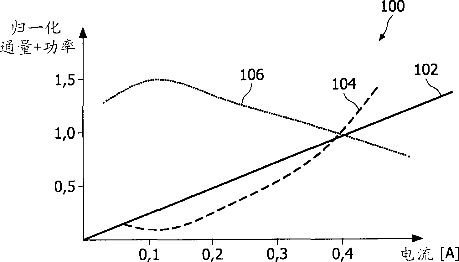
[0034] The methods and devices according to the invention take advantage of the fact that the luminous efficacy and luminous flux efficiency of a solid state lighting unit depend on the driving power and luminous flux of the lighting unit. figure 1 A graph 100 illustrating the correlation betwe...


PUM


Abstract

Operating a lighting device by acquiring a target brightness level of at least one solid-state lighting unit, and determining a reference driving current amplitude for obtaining the target brightness level. If the reference driving current amplitude is below an optimum driving current amplitude, the solid-state lighting unit is operated at the optimum driving current amplitude, which is pulse-width modulated to obtain the target brightness level.

Description

technical field [0001] The present invention generally relates to solid state lighting and methods of operating solid state lighting units. Background technique [0002] Solid state lighting has become an important feature in the lighting market. Solid State Lighting (SSL) units such as Light Emitting Diodes (LEDs) and Organic Light Emitting Diodes (OLEDs) provide low cost lighting and are thus used in the general lighting market. Solid state light sources provide light of a certain wavelength. These wavelengths depend on the materials used (ie semiconductors) and the environmental characteristics of the SSL unit. In addition, solid state light sources can have high luminous efficacy (efficacy), but this is also a function of temperature and driving method. [0003] In current lighting applications, it is desired that the lumen output of solid state light sources be at a maximum. Therefore, solid-state light sources are driven with the maximum allowable magnitude of curr...

Claims


Application Information

Patent Timeline
Patent Type & Authority Applications(China)
IPC IPC(8): H05B33/08H05B44/00
CPCH05B33/0818H05B33/0848H05B45/14H05B45/375
Inventor B·阿克曼D·亨特C·马蒂尼G·索尔兰德M·温特
Owner KONINK PHILIPS ELECTRONICS NV
Why Eureka
Try Eureka