Electrowetting display

An electrowetting display and electrode technology, which is applied in the direction of instruments, optics, optical components, etc., can solve the problem of low contrast of the display screen and achieve the effect of improving the contrast

Inactive Publication Date: 2009-05-06
INNOCOM TECH SHENZHEN +1
View PDF0 Cites 4 Cited by
  • Summary
  • Abstract
  • Description
  • Claims
  • Application Information

AI Technical Summary

Problems solved by technology

[0011] In order to solve the problem of low contrast of the display screen of the electrowetting display in the prior art, the present invention provides an electrowetting display with high contrast

Method used


Image

  • Electrowetting display
  • Electrowetting display
  • Electrowetting display

Examples


Embodiment Construction

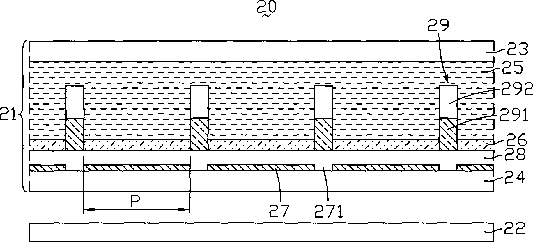
[0023] see image 3 , is a schematic cross-sectional view of the electrowetting display according to the first embodiment of the present invention when it displays a dark state. The electrowetting display 20 includes a display panel 21 and a backlight module 22 opposite to the display panel 21 . The backlight module 22 provides uniform planar backlight to the display panel 21 .

[0024] The display panel 21 includes a first substrate 23, a second substrate 24, and a first fluid 25, a second fluid 26, a plurality of electrodes 27, a A water-repellent insulating layer 28 and a plurality of partition walls 29 .

[0025] The plurality of electrodes 27 are made of transparent conductive material, such as indium tin oxide or indium zinc oxide. The electrodes 27 are arranged in a matrix on the surface of the second substrate 24 , each electrode 27 defines a pixel area P, and a gap 271 is formed between two adjacent pixel areas.

[0026] The water-repellent insulating layer 28 is ...


PUM


Abstract

The invention relates to an electric moistening display which is composed of a base board, a flow body arranged on the base board, and at least one insulation wall arranged on the base board, wherein each insulation wall is composed of materials which can absorb light rays. The electric moistening display can effectively improve the contrast gradient.

Description

technical field [0001] The invention relates to an electrowetting display. Background technique [0002] Electrowetting display is a newly developed display in recent years, which has the characteristics of low power consumption, wide viewing angle and high response speed. Therefore, electrowetting displays are very suitable for application in portable electronic products. [0003] see figure 1 , is a schematic cross-sectional view of an electrowetting display in the prior art when it displays a dark state. The electrowetting display 10 includes a display panel 11 and a backlight module 12 opposite to the display panel 11 . The backlight module 12 provides uniform planar backlight to the display panel 11 . [0004] The display panel 11 includes a first substrate 13, a second substrate 14, and a first fluid 15, a second fluid 16, a plurality of electrodes 17, a A water-repellent insulating layer 18 and a plurality of partition walls 19 . [0005] The plurality of electr...

Claims


Application Information

Patent Timeline
Patent Type & Authority Applications(China)
IPC IPC(8): G02B26/02G09F9/37
Inventor 蔡宏璋陈松延
Owner INNOCOM TECH SHENZHEN
Why Eureka
Try Eureka