Sterile surgical adaptor

An adapter, non-sterile technology, applied in the direction of surgery, etc., to reduce costs, improve stability, and increase visibility

Active Publication Date: 2009-05-06
INTUITIVE SURGICAL OPERATIONS INC
View PDF12 Cites 63 Cited by
  • Summary
  • Abstract
  • Description
  • Claims
  • Application Information

AI Technical Summary

Problems solved by technology

Also, in open surgery, there is often not enough space around the surgical site to place more than one or two surgical manipulators, thus forci

Method used


Image

  • Sterile surgical adaptor
  • Sterile surgical adaptor
  • Sterile surgical adaptor

Examples


Embodiment Construction

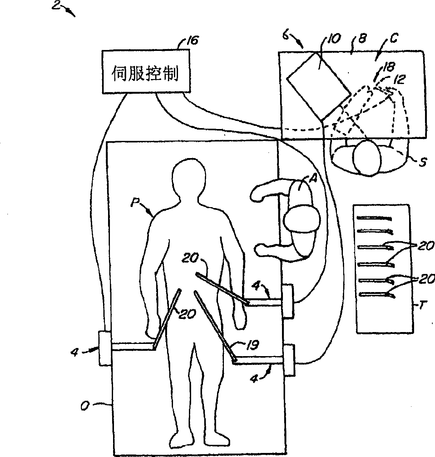
[0052] [0051] The present invention provides multi-component systems and methods for performing robotic-assisted surgical procedures on a patient, including in particular open surgical procedures, neurosurgical procedures such as stereotactic surgery, and surgical procedures such as laparoscopic, arthroscopic, thoracoscopic and other endoscopic procedures. The systems and methods of the present invention are particularly useful as part of a telerobotic surgery system that allows a surgeon to manipulate surgical instruments via servo mechanisms from a remote location away from the patient. For this purpose, the manipulator device or slave device of the present invention is typically driven by a motion-equivalent master device to form a telepresence system with force feedback. A description of a suitable slave-master system is found in US Patent Application Serial No. 08 / 517,053, filed August 21, 1995, which is incorporated herein by reference.

[0053] [0052] Referring to the ...


PUM


Abstract

A sterile adaptor (300), a sterile drape (404) with the integrated sterile adaptor, and a telerobotic surgical system (200) including the sterile drape (256) with a drape interface are provided. The adaptor, drape, and system allow for draping portions of a telerobotic surgical system to maintain a sterile barrier between the sterile surgical field and the non-sterile robotic system while also providing an interface for transferring mechanical and electrical energy and signals between a robotic arm and a surgical instrument (250) in the sterile field.

Description

[0001] Cross References to Related Applications [0002] [0001] This application claims the benefit of US Provisional Application No. 60 / 752,472, filed December 20, 2005, the disclosure of which is hereby incorporated by reference in its entirety. [0003] [0002] This application is a continuation-in-part of pending U.S. Patent Application No. 11 / 314,040, filed December 20, 2005, which is a pending U.S. Patent Application No. 10 / 922,346, filed August 19, 2004 Partial continuation of application. U.S. Patent Application No. 10 / 922,346 is a continuation of U.S. Patent Application No. 10 / 004,399, filed October 30, 2001, which is a continuation of U.S. Patent Application No. 09 / 406,360, filed September 28, 1999, the current A continuation of U.S. Patent No. 6,346,072, U.S. Patent No. 6,346,072 is a continuation of U.S. Patent Application No. 08 / 975,617, filed November 21, 1997, now U.S. Patent No. 6,132,368, which claimed Priority to U.S. Provisional Application No. 60 / 033,321, fi...

Claims


Application Information

Patent Timeline
IPC IPC(8): A61B1/00
Inventor S·C·安德森J·奥尔班R·德文根佐
Owner INTUITIVE SURGICAL OPERATIONS INC
Why Eureka
Try Eureka