Cut die feeding mechanism

A feeding mechanism and blanking die technology, applied in metal processing equipment, feeding devices, manufacturing tools, etc., can solve the problems of coil material affecting the accurate feeding of coil material and hindering the slippage of waste material, so as to achieve the effect of improving production efficiency.

Active Publication Date: 2009-05-13
SICHUAN CHENGFEI INTEGRATION TECH
View PDF0 Cites 4 Cited by
  • Summary
  • Abstract
  • Description
  • Claims
  • Application Information

AI Technical Summary

Problems solved by technology

[0003] In view of the above situation, the present invention provides a feeding mechanism for the blanking die, which not only solves the problem that the coil material is too long to affect the accurate feeding of the coil material, but also overcomes the problem that the existing fixed positioner or lifting block hinders the waste material from sliding out, thereby Improve mold opening accuracy and production efficiency

Method used


Image

  • Cut die feeding mechanism
  • Cut die feeding mechanism
  • Cut die feeding mechanism

Examples


Embodiment Construction

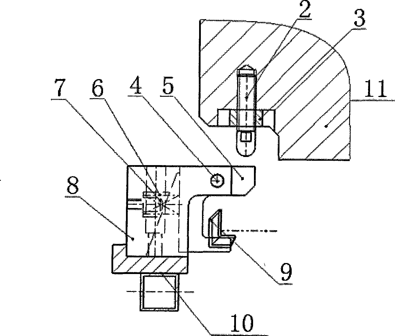
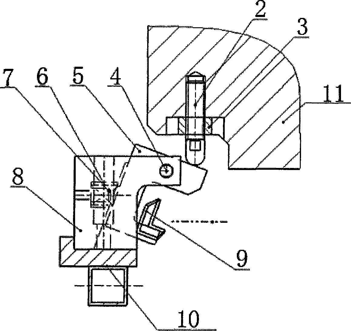
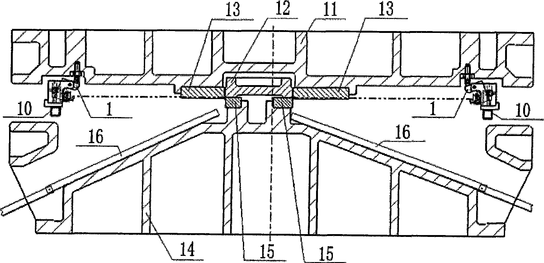
[0017] The invention proposes a feeding mechanism for a blanking die. Lifting block 5 is installed on the fixed support 8, and is connected with support shaft pin 4, and support 8 is provided with lifting block reset device; 11 is provided with the ejector pin that cooperates with material lifting block 5. When working, the ejector rod moves downward with the upper die base 11. When cutting materials, the ejector rod is pushed against the outside of the lifting block 5. The lifting block 5 rotates with the shaft pin 4 as the center of the circle. Block 5 exits.

[0018] The reset device for lifting the material block is a spring reset mechanism, such as a torsion spring mechanism, an extension spring mechanism, and a compression spring mechanism, and other mechanisms such as a rotary positioning block can also be used to realize the reset of the material lifting block 5 . The spring return mechanism shown in the figure includes a mandrel 7 installed in the support 8 and a sp...


PUM


Abstract

The invention discloses a feeding mechanism for a cut die, which comprises a screw, a nut, a shaft pin, a plate lifting block, a spring, a mandrel, a bearer and a supporting plate. The lifting block can rotate around the shaft pin, and the spring is positioned by the mandrel and pushes the lifting block to return to the original position. The feeding mechanism can ensure that a plate is accurately fed while a cut die blank is kept off without influence on sliding-out of scraps, thereby improving production efficiency.

Description

Technical field: [0001] The invention belongs to the technical field of moulds, in particular to a blanking die feeding mechanism for an uncoiling blanking die. Background technique: [0002] Existing uncoiling die comprises upper mold base, upper die cutting edge, feeder, lower mold base, lower die cutting blade, waste slide plate that the both sides of lower mold base are arranged obliquely. When working, the upper mold seat moves downward, the upper and lower cutting blades of the upper mold cooperate to cut off the coil material, and the scraps cut off from the side slide down from the scrap slide and are sent away under the action of the inclined plane. When the length of the coil material is long, the two ends will fall down, affecting the accurate feeding of the coil material, resulting in low mold opening accuracy. The general method used to solve this problem is to install fixed positioners or lifting blocks at both ends of the coil to realize the effect of lifting...

Claims


Application Information

Patent Timeline
IPC IPC(8): B21D43/02B21D28/14
Inventor 徐慧明
Owner SICHUAN CHENGFEI INTEGRATION TECH
Why Eureka
Try Eureka