Feeder

A feeder and rack technology, applied in the field of stainless steel ceiling gusset processing, can solve the problems of low efficiency, unstable quality and high production cost, and achieve the effects of stable processing quality, low processing cost and improving production efficiency

Pending Publication Date: 2019-08-27
佛山市国铝五金制品有限公司
View PDF0 Cites 2 Cited by
  • Summary
  • Abstract
  • Description
  • Claims
  • Application Information

AI Technical Summary

Problems solved by technology

The transmission of semi-finished products between each process is carried out manually. This production method has low efficiency, high production cost and unstable quality.

Method used


Image

  • Feeder
  • Feeder

Examples


Embodiment Construction

[0014] Now in conjunction with accompanying drawing and embodiment the present invention is described in further detail:

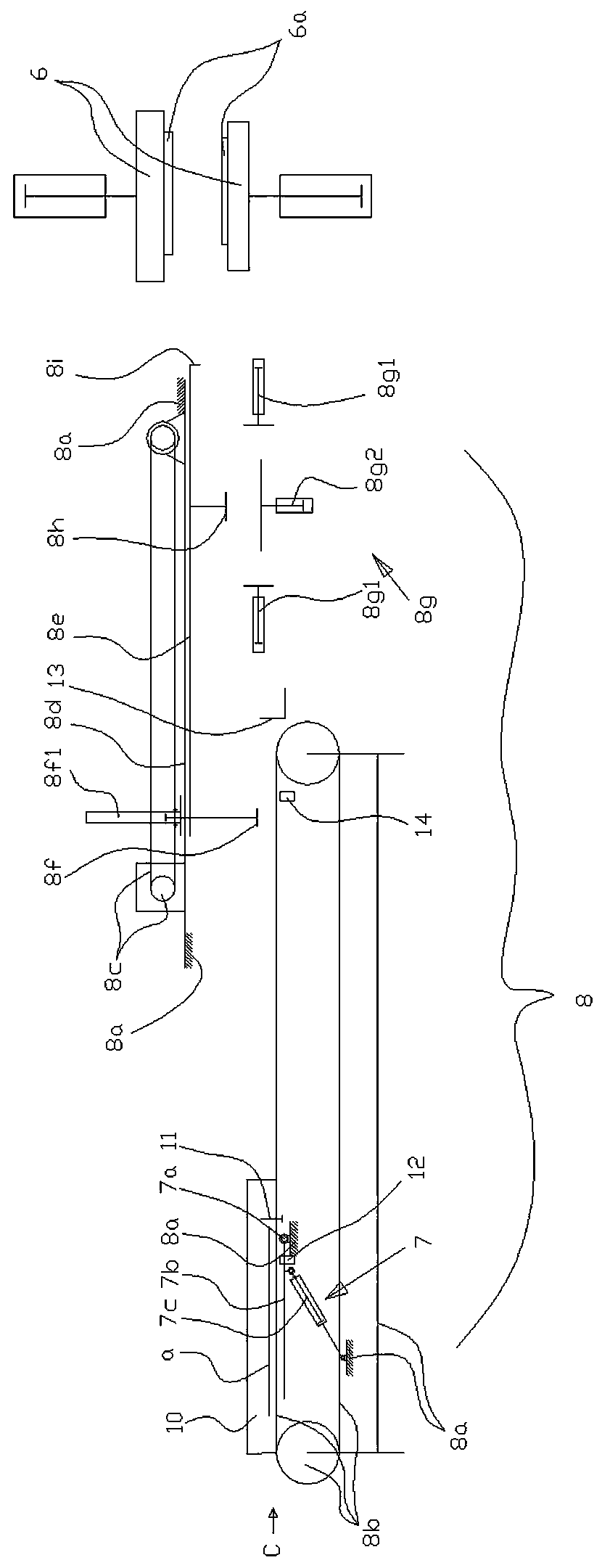
[0015] Such as figure 1 As shown, the feeder 8 of the present invention includes a power transmission belt 8b arranged on both sides of the frame 8a, a first sucker mechanism 8f driven by a power 8c through a moving frame 8e moving back and forth along a track 8d, and a plate positioning mechanism located above the power transmission belt 8b. The mechanism 8g and the second sucker mechanism 8h located above the plate positioning mechanism 8g are driven by the power 8c through the moving frame 8e moving back and forth along the track 8d.

[0016] The front end of the power transmission belt 8b is provided with a turning machine 7, and the turning machine includes a turning plate 7b that is arranged on the frame 8a and is located between the power transmission belts 8b on both sides along the rotating shaft 7a, and a power mechanism 7c that drives the turnin...


PUM


Abstract

A feeder is characterized by comprising power transmission belts arranged on two sides of a rack, a first sucker mechanism located above the power transmission belts and driven by a power mechanism tomove forwards and backwards along a rail, a plate positioning mechanism and a second sucker mechanism located above the plate positioning mechanism and driven by the power mechanism to move forwardsand backwards along the rail. Compared with the prior art, the feeder can achieve conveying of semi-finished products between punch presses or hydraulic machines, can accurately feed plates into the punch presses or the hydraulic machines and has the advantages of being capable of improving the production efficiency and guaranteeing stability of machining quality and low in machining cost.

Description

technical field [0001] The invention relates to a stainless steel ceiling gusset processing technology. Background technique [0002] The existing metal ceiling gussets on the market are made of aluminum gussets / plastic steel plates / iron plates, etc., and are processed by manual stamping or semi-automatic methods through several punches or hydraulic presses and other equipment according to multiple processes. The transmission of semi-finished products between each process is carried out manually. This production method has low efficiency, high production cost and unstable quality. Contents of the invention [0003] The purpose of the present invention is to provide a feeder that can realize the transfer of semi-finished products between punches or hydraulic presses and accurately feed them into the punches or hydraulic presses, so as to improve production efficiency, ensure stable processing quality and low processing cost. [0004] The present invention is achieved in th...

Claims


Application Information

Patent Timeline
IPC IPC(8): B21D43/00B21D43/02B21D43/18B21D43/14B21D45/02
CPCB21D43/003B21D43/026B21D43/027B21D43/18B21D43/145B21D45/02
Inventor 蒋中成
Owner 佛山市国铝五金制品有限公司
Why Eureka
Try Eureka