Machine tool fluid pressure center frame

A center frame and liquid technology, which is applied in the direction of grinding machines, machine tools designed for grinding the rotating surface of workpieces, grinding workpiece supports, etc., can solve the problems of insufficient support accuracy, and achieve high support accuracy, vibration suppression, absorption and vibration Effect

Inactive Publication Date: 2009-05-13
HEFEI UNIV OF TECH
View PDF0 Cites 21 Cited by
  • Summary
  • Abstract
  • Description
  • Claims
  • Application Information

AI Technical Summary

Problems solved by technology

[0003] In order to solve the problem of insufficient support accuracy in precision machining of shaft p

Method used


Image

  • Machine tool fluid pressure center frame
  • Machine tool fluid pressure center frame
  • Machine tool fluid pressure center frame

Examples


Embodiment 1

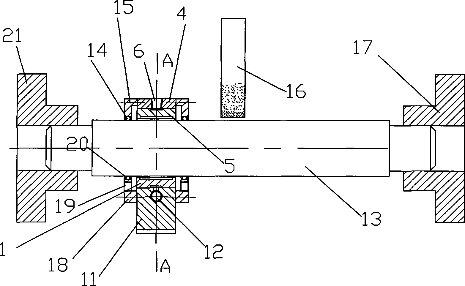
[0022] The workpiece to be processed is a precision spindle with a relatively large length and diameter, high precision machining of the outer circle, and large production batches.

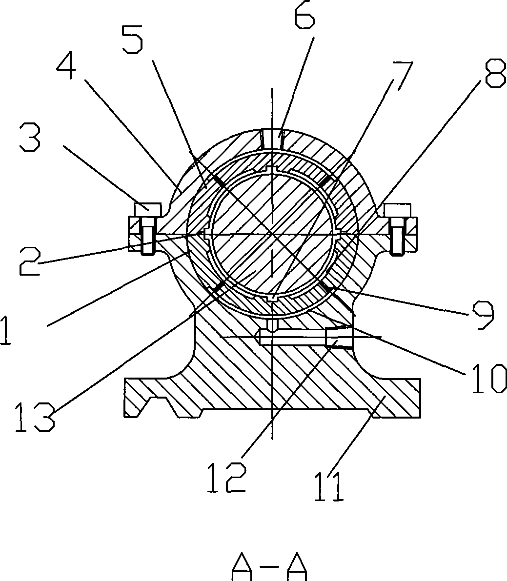
[0023] see figure 1 and figure 2 One end of workpiece 13 to be processed is supported and clamped by machine tool spindle chuck 21, and the other end is supported by tailstock support 17, and emery wheel 16 grinds the middle surface of workpiece 13 to be processed. A hydrostatic center frame is installed on the ground part of the processed workpiece 13. The hydrostatic center frame of the machine tool includes an upper gland 4 and a center support 11 fixed by bolts 3. The upper bearing bush 5 of the center frame Fixedly connected to the radial inner side of the upper gland 4, the lower bearing bush 1 is fixedly connected to the concave semicircular surface of the central support 11, the upper bearing bush 5 and the lower bearing bush 1 are provided with a positioning notch 2, and a positioning n...

Embodiment 2

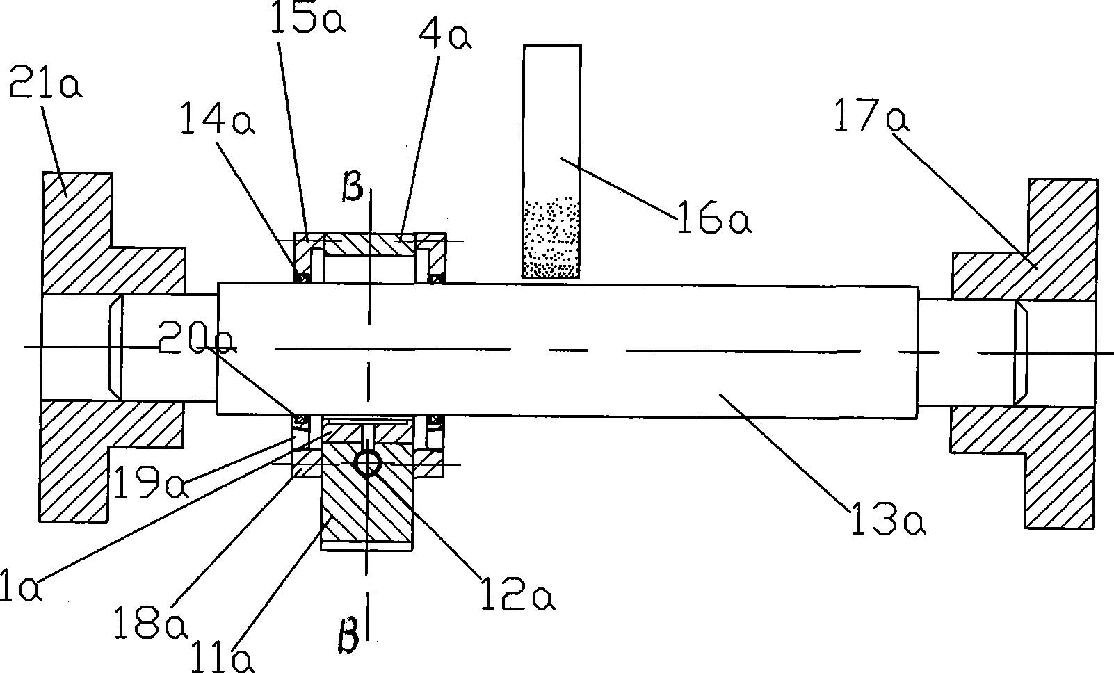
[0028] The workpiece to be processed is a certain kind of roll, which has a relatively large length and diameter, heavy weight, and requires high machining accuracy of the outer circle. Due to the large weight of the workpiece, the bending deformation caused by its own weight is the main factor affecting the accuracy in the finishing process. For the convenience of use, the workpiece is supported by the static pressure steady rest with only the lower support, so as to reduce the bending deformation caused by the self-weight during the finishing process.

[0029] see image 3 and Figure 4 One end of the workpiece 13a to be processed is supported and clamped by the machine tool spindle chuck 21a, and the other end is supported by the tailstock support 17a. The grinding wheel 16a grinds the surface of the workpiece 13a to be processed. The ground part of the workpiece 13a to be processed is installed with a hydrostatic center frame. The center frame has only one lower bearing ...


PUM


Abstract

The invention relates to a liquid static pressure central support of a machine tool for processing shaft-type parts, which solves the problem that the bearing precision in the precision machining of the shaft-type parts is insufficient. The central support is characterized in that a lower bearing bush is arranged on the central support, an upper bearing bush is arranged on the inner lateral surface of an upper gland in the radial direction, bearing grooves are formed on the working planes of the upper bearing bush and the lower bearing bush, and an oil returning groove is formed between adjacent bearing grooves; arc oil grooves are formed on the back of the upper bearing bush and the lower bearing bush; orifices are formed on the bearing grooves, and the orifices are communicated with the bearing grooves and the arc oil grooves; a lower oil inlet is formed on the central support; upper semi-end covers are arranged on both lateral surfaces of the upper gland in the axial direction respectively, and lower semi-end-covers are arranged on both lateral surfaces of the lower concave semicircular surface of the central support in the axial direction respectively. The liquid static pressure central support adopts the liquid static pressure technology to directly support work pieces, and the rigid direct contact does not exist between the central support and the work pieces; therefore, the invention has the following advantages: the abrasion is not generated on the surface of the work pieces, the vibration of the work pieces supported can be absorbed and refrained, the bearing precision is higher, and the liquid static pressure central support is suitable for the precision machining of the shaft-type parts.

Description

technical field [0001] The invention relates to a center frame or a tool rest of a machine tool for machining shaft parts. Background technique [0002] When turning or grinding slender shafts, in order to reduce the bending deformation of the processed parts under the action of gravity or cutting force, the center frame or the tool rest are often used to assist the processed parts. The support of the existing center frame or tool rest to the processed parts is a rigid support. The center frame or the tool rest directly contacts the workpiece at the support point, such as the commonly used three-point contact center frame with rollers. , the rollers of the center frame are directly against the surface of the supported parts. Due to the rigid contact support of the existing steady rest or tool rest, there are the following deficiencies: the ability to absorb the vibration of the workpiece is poor, and even the additional vibration of the workpiece is generated, especially wh...

Claims


Application Information

Patent Timeline
IPC IPC(8): B23Q1/76B23B25/00B24B5/35B24B5/04B24B41/06
Inventor 黄斌
Owner HEFEI UNIV OF TECH
Why Eureka
Try Eureka