
Magnetic resonance imaging method and apparatus thereof

A magnetic resonance imaging and imaging technology, which is applied in the direction of magnetic resonance measurement, measurement using nuclear magnetic resonance imaging system, and magnetic variable measurement, etc., which can solve the problems of detection interference and no imaging provided.

Inactive Publication Date: 2009-05-13
INST OF ELECTRICAL ENG CHINESE ACAD OF SCI
View PDF1 Cites 26 Cited by
  • Summary
  • Abstract
  • Description
  • Claims
  • Application Information

AI Technical Summary

Problems solved by technology

[0011] Obviously, the problem with this method is that the requirements for the environment are very strict. If the surrounding stray magnetic field reaches the magnitude of the magnetic field strength generated by the atomic magnetic moment during detection, it will interfere with the detection.
Since a large amount of imaging is carried out for stationary objects, this document does not provide imaging for stationary imaging targets, and the method of using optically pumped magnetic resonance probes to read signals

Method used


Image

  • Magnetic resonance imaging method and apparatus thereof
  • Magnetic resonance imaging method and apparatus thereof
  • Magnetic resonance imaging method and apparatus thereof

Examples


Embodiment Construction

[0030] The present invention will be further described below in conjunction with the accompanying drawings and specific embodiments.

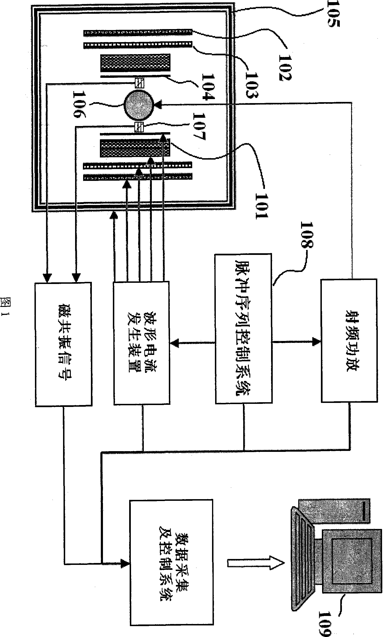
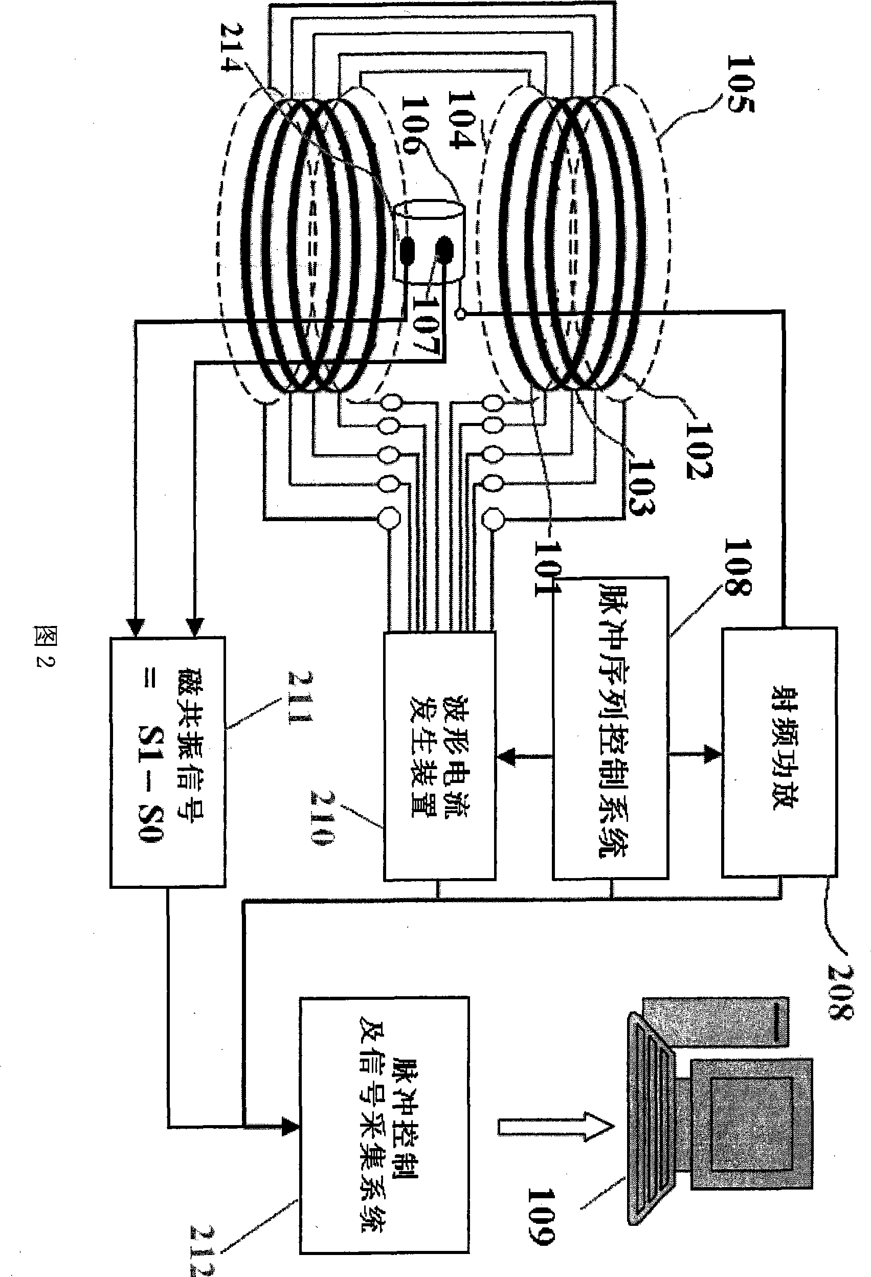
[0031] As shown in FIG. 1 , the method of the present invention is: firstly apply a strong polarizing magnetic field of 1000-5000 Gauss to the imaging target, and the polarizing magnetic field is generated by a polarizing magnet 101 . After 50-3000 ms, the polarized magnetic field is turned off, and an extremely low encoding magnetic field of 20-100 Gauss is applied to the imaging target. The encoding magnetic field is generated by the encoding magnet 102 . Under this encoding magnetic field, radio frequency excitation is performed on the imaging target and a gradient magnetic field is applied for spatial encoding. The gradient magnetic field is generated by the three-dimensional magnetic field gradient coil 103, and the required radio frequency field is generated by the radio frequency coil 106, and then the encoding magnetic field, the gradien...


PUM


Abstract

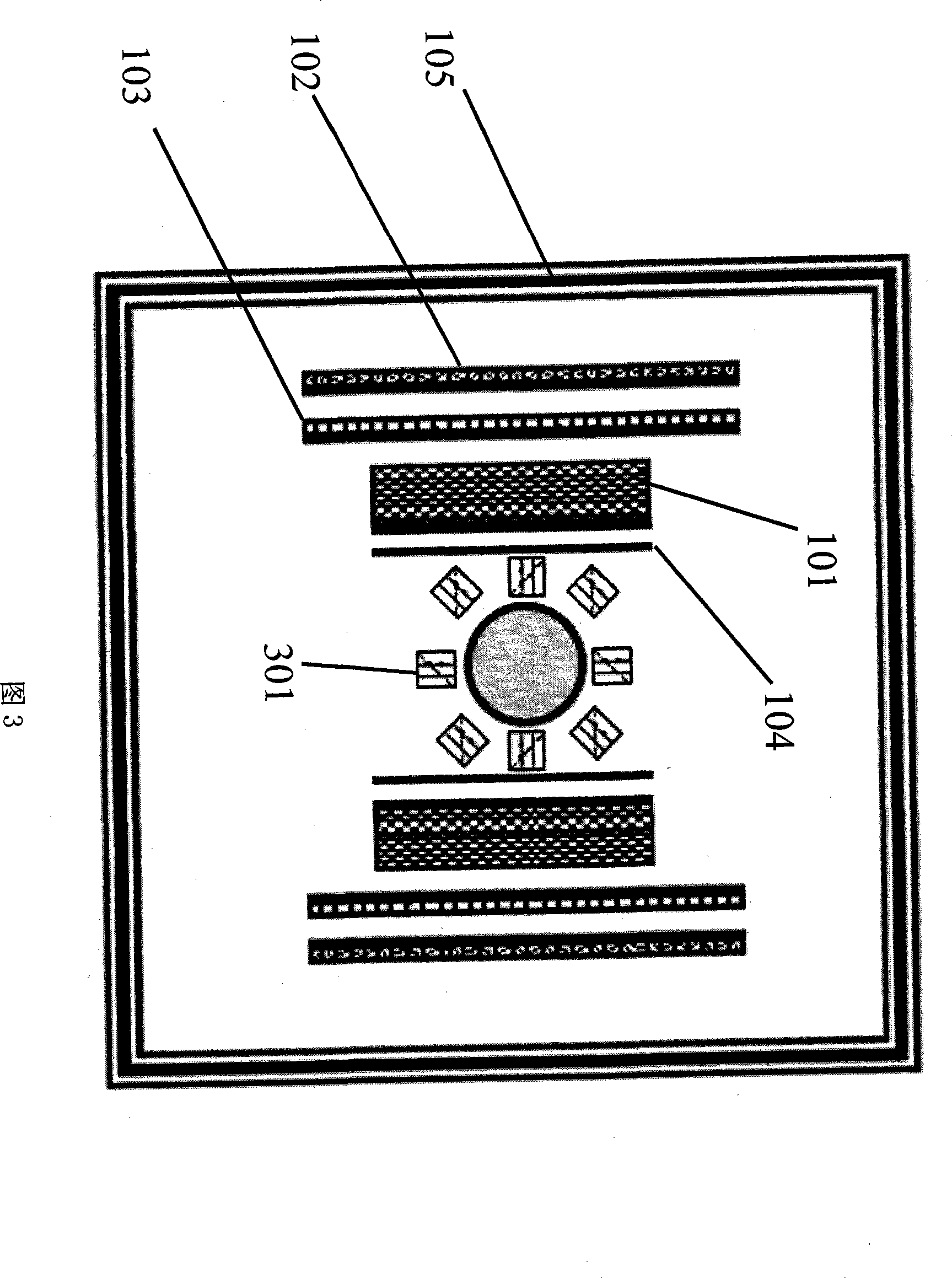
The invention discloses a magnetic resonance imaging method. The method comprises the following steps: applying a strong polarizing magnetic field to an imaging object, closing the polarizing magnetic field, applying a low-polar encoding magnetic field to the sample, applying a gradient magnetic field to the sample for space coding in this magnetic field, closing the encoding magnetic field, reading magnetic resonance signals by an optomagnetic resonance method in an nT-level magnetic field environment, and rebuilding images. The device comprises a polarizing magnet (101) for generating the polarizing magnetic field with controllable magnetic field, an encoding magnet (102) for generating the encoding magnetic field with the controllable magnetic field, a 3D gradient system (103) for generating the gradient magnetic field, an nT coil (104) for generating the nT-level magnetic field, a magnetic shielding system (105), a radio frequency coil (106), an optomagnetic probe (107), a pulse sequence control system (108) and an image processing computer (109). The imaging object and the optomagnetic probe (107) are arranged in the encoding magnet (102) and the polarizing magnet (101).

Description

technical field [0001] The invention relates to a magnetic resonance imaging (MRI) system, in particular to a novel magnetic resonance imaging method and device thereof. Background technique [0002] When the current magnetic resonance imaging system works, the human body needs to be placed in a strong static magnetic field, and the atomic nuclei in some areas of the human body are excited by sending radio frequency pulses to the human body. After the radio frequency field is removed, these excited nuclei radiate radio frequency signals, which are received by the antenna. When a gradient magnetic field is added in this process, the spatial distribution information of the human body can be obtained through radio frequency signals, thereby reconstructing a two-dimensional or three-dimensional image of the human body. [0003] Since the signal-to-noise ratio of the image is related to the magnetic field strength, the stronger the magnetic field strength, the higher the signal-...

Claims


Application Information

Patent Timeline
IPC IPC(8): G01R33/56
Inventor 杨文晖王慧贤胡丽丽王铮
Owner INST OF ELECTRICAL ENG CHINESE ACAD OF SCI
Learn More