
A photographing device of a display device and a photographing method thereof

A technology of a display device and a shooting device, applied in photography, camera body, shutter, etc., can solve problems such as affecting the shooting quality, all black, stripes, etc., and achieve the effect of good shooting quality, good synchronization effect, and convenient use.

Inactive Publication Date: 2012-02-08
GUANGDONG VTRON TECH CO LTD
View PDF1 Cites 0 Cited by
  • Summary
  • Abstract
  • Description
  • Claims
  • Application Information

AI Technical Summary

Problems solved by technology

[0002] With the development of computer information technology, the technical application of various electronic equipment is advancing by leaps and bounds, and the application of display equipment for information display and communication is showing a trend of diversification. For example, from the initial TV to the current large screen display system, and in the application of the display device, it is necessary to capture the images displayed by the display device in various occasions, so as to be able to analyze and process these images, for example, it is necessary to save the captured image, However, due to the different display principles of each display device, for example, LCD, PDP and other display devices are based on field and frame scan display devices, while CRT and projection display devices are based on In other words, it is a display device with an unknown refresh rate. When shooting these display devices, the expected effect is often not achieved, and it is prone to flickering, stripes, image misalignment, partial black, or even completely black.
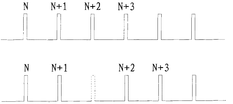
A shooting method in the prior art is to continuously send time beat signals between the shooting device and the display device to achieve the purpose of synchronization, and to shoot during synchronization. This method can achieve better shooting during synchronization. The effect, however, is to some extent increase the burden on the equipment due to the non-stop sending of time tick signals, in addition, see figure 1 Shown is a synchronous pulse schematic diagram of the shooting method in the prior art. During the transmission of the synchronous signal, due to problems such as interference, it is likely to cause a pulse signal to be lost, such as figure 1 The pulse signal shown by the dotted line in the center is usually set as a multiple of the refresh cycle of the display device when setting the exposure time. If the pulse signal is lost during the shooting process, the actual exposure time will be longer than the set time. The exposure time is one more refresh cycle, which affects the shooting quality

Method used


Image

  • A photographing device of a display device and a photographing method thereof
  • A photographing device of a display device and a photographing method thereof
  • A photographing device of a display device and a photographing method thereof

Examples


Embodiment 1

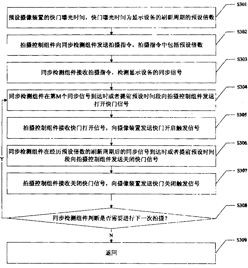
[0022] see image 3 As shown, it is a schematic flowchart of Embodiment 1 of the shooting method of the shooting device of the display device of the present invention. In this embodiment, the description mainly focuses on the camera device that needs to receive a trigger signal to close the shutter before closing the shutter.

[0023] Such as image 3 As shown, in this embodiment, it specifically includes steps:

[0024] Step S301: preset the shutter exposure time of the camera device, the shutter exposure time can be set as a multiple of the refresh cycle of the display device, since the specific refresh cycle of the display device may not be known in advance, so the shutter exposure time can be directly set at this time The multiple value is enough. When setting, receive the value input by the user and set the value as the preset multiple of the refresh cycle of the display device. The product of the preset multiple and the refresh cycle is the shutter exposure time. Then, ...

Embodiment 2

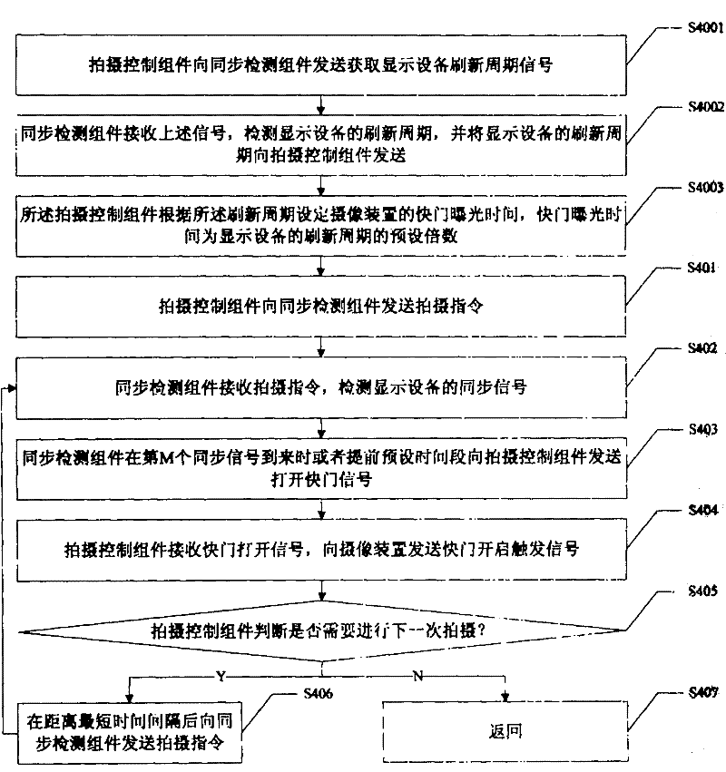
[0050] see Figure 4 As shown, it is a schematic flow chart of Embodiment 2 of the shooting method of the shooting device of the display device of the present invention. In this embodiment, the camera device that can automatically close the shutter without receiving a trigger signal to close the shutter is mainly described.

[0051] Such as Figure 4 As shown, in this embodiment, it specifically includes steps:

[0052] Step S401: the shooting control component sends a shooting instruction to the synchronization detection component, and enters step S402;

[0053] Step S402: The synchronization detection component receives the shooting instruction sent by the shooting control component, detects the synchronization signal of the display device, and enters step S403;

[0054] Step S403: The synchronization detection component sends an opening shutter signal to the shooting control component when the first preset number of synchronization signals arrives, and notifies the shooti...


PUM


Abstract

A photographing device of a display device and a photographing method thereof, the photographing device comprises a photographing control component connected to the photographing device, and a synchronous detection component connected to the display device, wherein the synchronous detection component detects the timing of the display device according to the photographing instruction of the photographing control component. synchronous signal, and according to the synchronous signal, send the shutter opening signal to the shooting control assembly, and the shutter opening signal of the shooting control assembly controls the opening of the shutter of the camera device. The component does not need to detect the synchronous signal of the display device from time to time, it can only detect after receiving the shooting instruction, and the shooting control component controls the opening of the shooting device according to the signal of the synchronous detection component. There will be a phenomenon of pulse signal loss to ensure better shooting quality, and you don’t need to care about the refresh cycle of the display device when shooting, which is convenient to use.

Description

technical field [0001] The invention relates to the field of photographing a display device, in particular to a photographing device of a display device and a photographing method thereof. Background technique [0002] With the development of computer information technology, the technical application of various electronic equipment is advancing by leaps and bounds, and the application of display equipment for information display and communication is showing a trend of diversification. For example, from the initial TV to the current large screen display system, and in the application of the display device, it is necessary to capture the images displayed by the display device in various occasions, so as to be able to analyze and process these images, for example, it is necessary to save the captured image, However, due to the different display principles of each display device, for example, LCD, PDP and other display devices are based on field and frame scan display devices, w...

Claims


Application Information

Patent Timeline
Patent Type & Authority Patents(China)
IPC IPC(8): G03B17/38G03B9/08G03B15/00
Inventor 徐响林
Owner GUANGDONG VTRON TECH CO LTD
Learn More