Outdoor high-voltage permanent magnet type vacuum circuit breaker
A vacuum circuit breaker, permanent magnet technology, applied in high voltage air circuit breakers, high voltage/high current switches, circuits, etc., can solve the problems of unbalance of the moving spindle, easy to malfunction, difficult to work correctly, etc. Effect
- Summary
- Abstract
- Description
- Claims
- Application Information
AI Technical Summary
Problems solved by technology
Method used
Image
Examples
Embodiment 1
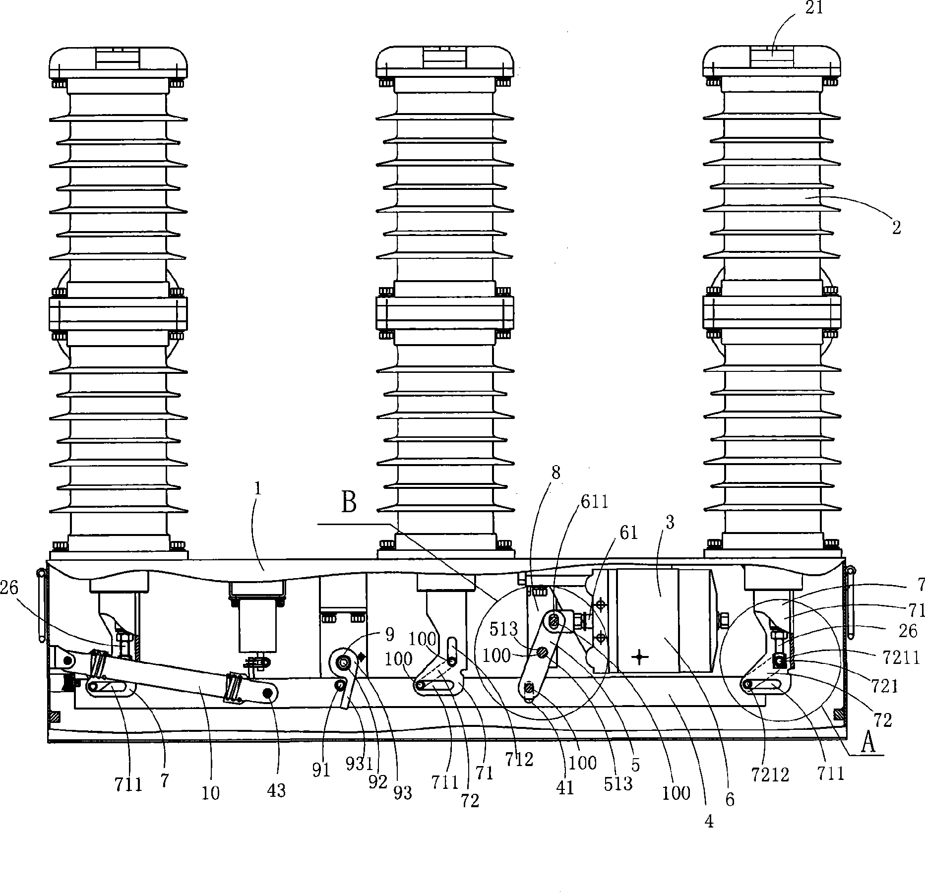
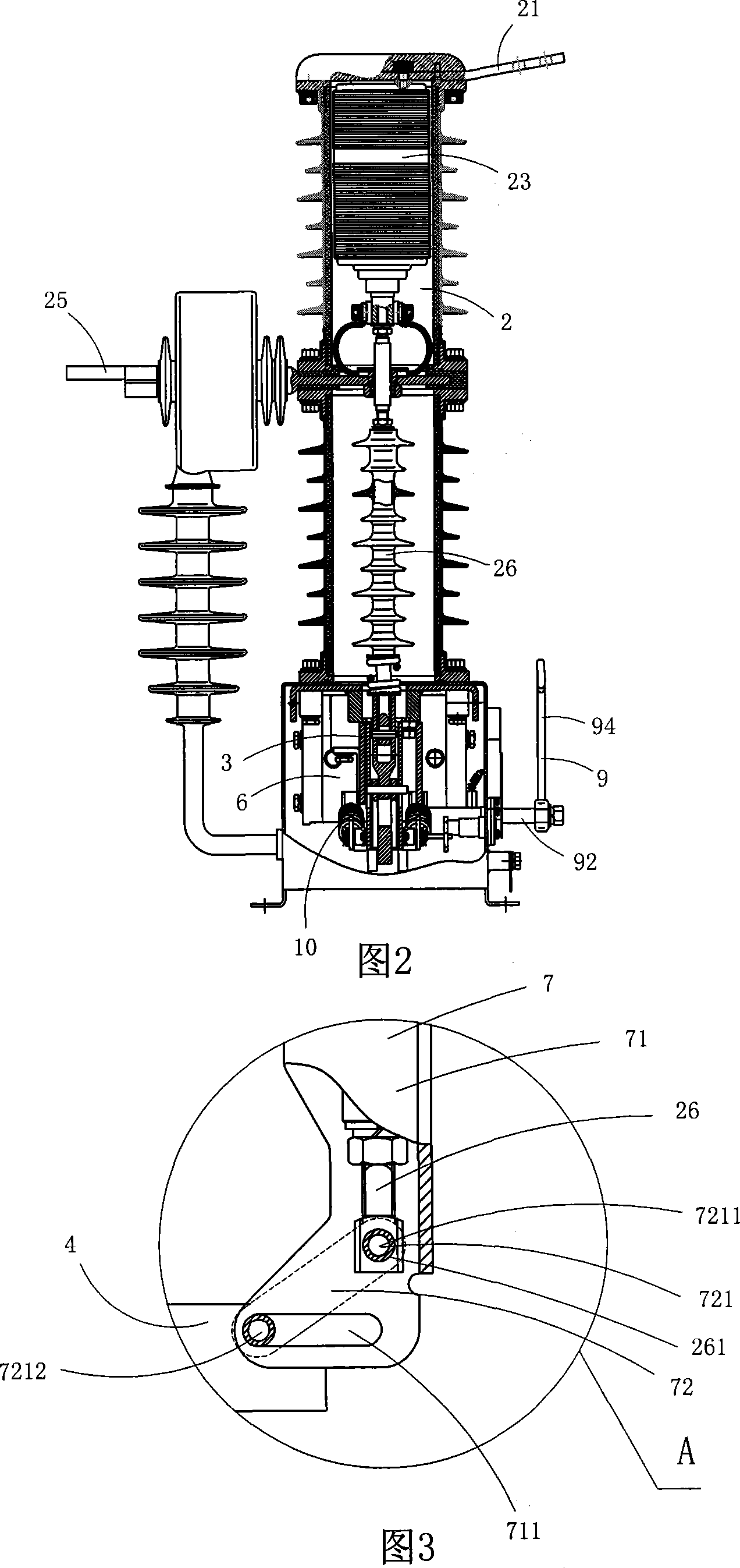
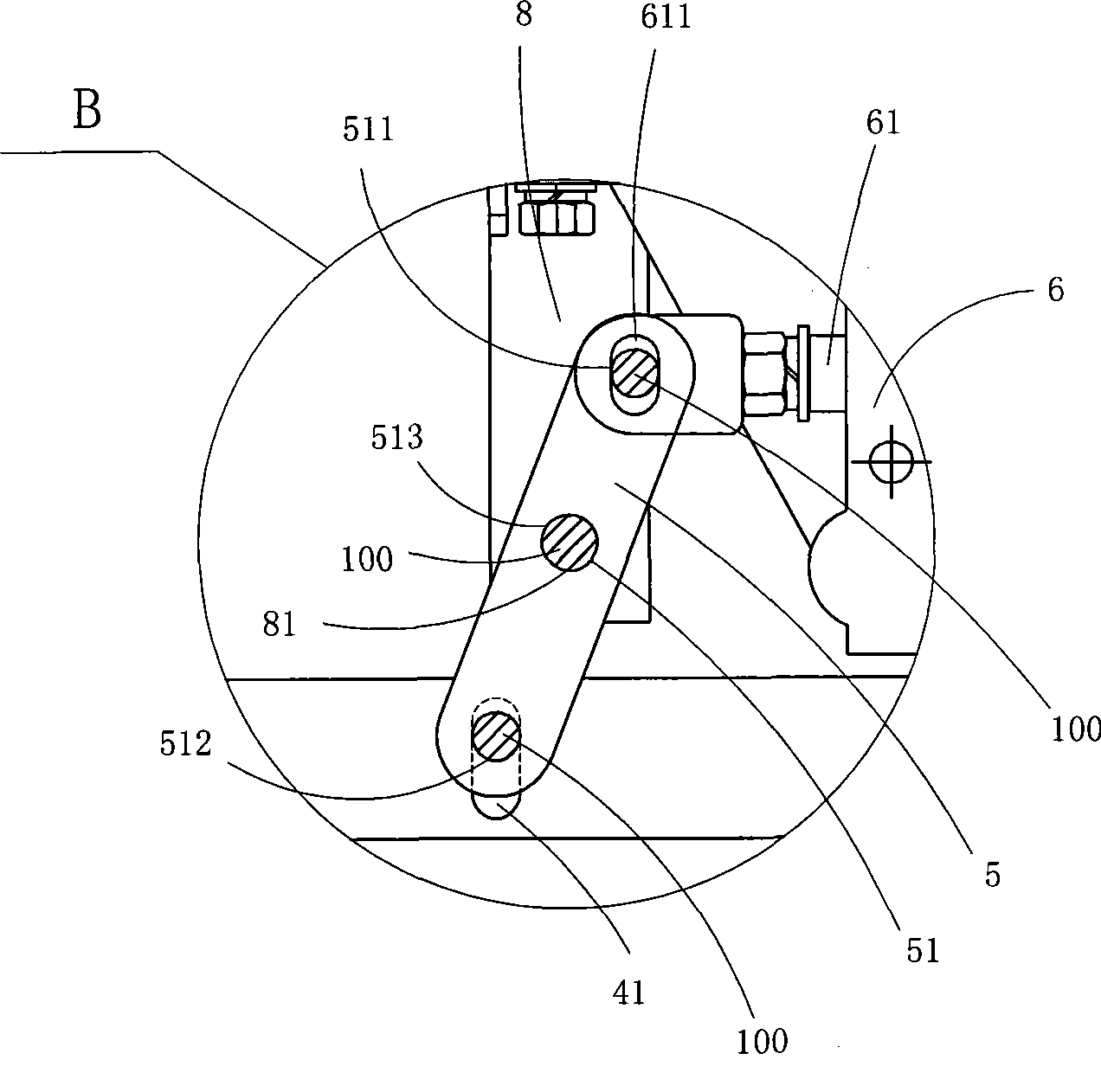
[0028] Figure 1 to Figure 4 A specific embodiment of the invention is shown in which, figure 1 It is a schematic structural diagram of the present invention; Fig. 2 is figure 1 A schematic diagram of the structure of the outdoor high-voltage permanent magnet vacuum circuit breaker when viewed from the side; Figure 3 is figure 1 Partial enlarged schematic diagram of A; Figure 4 yes figure 1 The partial enlarged schematic diagram of B.
[0029] This embodiment is an outdoor high-voltage permanent magnet vacuum circuit breaker, see figure 1 As shown in Fig. 2, an outdoor high-voltage permanent magnet vacuum circuit breaker includes a base 1, three poles 2 disposed on the base 1 and a permanent magnet operating mechanism 3 disposed in the base 1; each pole 2 The outlet bar 21, the static contact electrically connected to the outlet bar 21, the vacuum interrupter 23, the moving contact, the terminal clamp 25 electrically connected to the moving contact, and the insulating pu...
Embodiment 2
[0038] Fig. 5 is a partially enlarged schematic view of the second structure of the present invention, showing a second specific implementation manner of the present invention.
[0039] This embodiment is basically the same as Embodiment 1, except that: when the shaft holes 261 near the bottom ends of the insulating rods 26 are waist-shaped holes extending in the vertical direction, it is more conducive to effectively ensuring the verticality of the insulating push rods. The movement will not be affected by the displacement of the horizontal movement of the drive shaft, thus ensuring the stability and reliability of the opening and closing action.
Embodiment 1 and Embodiment 2
[0040] Embodiment 1 and embodiment 2 have obvious advantages:
[0041] (1) In Embodiment 1 and Embodiment 2, the permanent magnet operating mechanism 3 includes a driving rod 61 arranged in the horizontal direction, and the end of the driving rod 61 is provided with a limit hole 611, and the limit The hole 611 is a waist-shaped hole extending in the vertical direction, and the end of the driving rod 61 is connected to the driving arm 5 through the limiting hole 611; The other end of the drive arm 5 is rotatably connected to the drive spindle hole 41, which is a waist-shaped hole extending in the vertical direction; when the switch is opened and closed in Embodiment 1 and Embodiment 2, the permanent magnet operating mechanism The driving arm drives the transmission main shaft, and then drives the corresponding insulating pull rod 26 to reciprocate in the vertical direction through the transmission mechanism to realize the opening and closing operation; since the limit hole at t...
PUM
 Abstract
Description
Claims
Application Information
 - R&D
- Intellectual Property
- Life Sciences
- Materials
- Tech Scout
- Unparalleled Data Quality
- Higher Quality Content
- 60% Fewer Hallucinations
Browse by: Latest US Patents, China's latest patents, Technical Efficacy Thesaurus, Application Domain, Technology Topic, Popular Technical Reports.
© 2025 PatSnap. All rights reserved.Legal|Privacy policy|Modern Slavery Act Transparency Statement|Sitemap|About US| Contact US: help@patsnap.com


