

Novel apparatus used for film engraving and dotting of thin-film solar cell
Patent Information
- Authority / Receiving Office
- CN · China
- Patent Type
- Patents(China)
- Current Assignee / Owner
- WUHAN LINGYUN PHOTOELECTRONICS SYST
- Publication Date
- 2010-08-11
- Estimated Expiration
- Not applicable · inactive patent
Smart Images
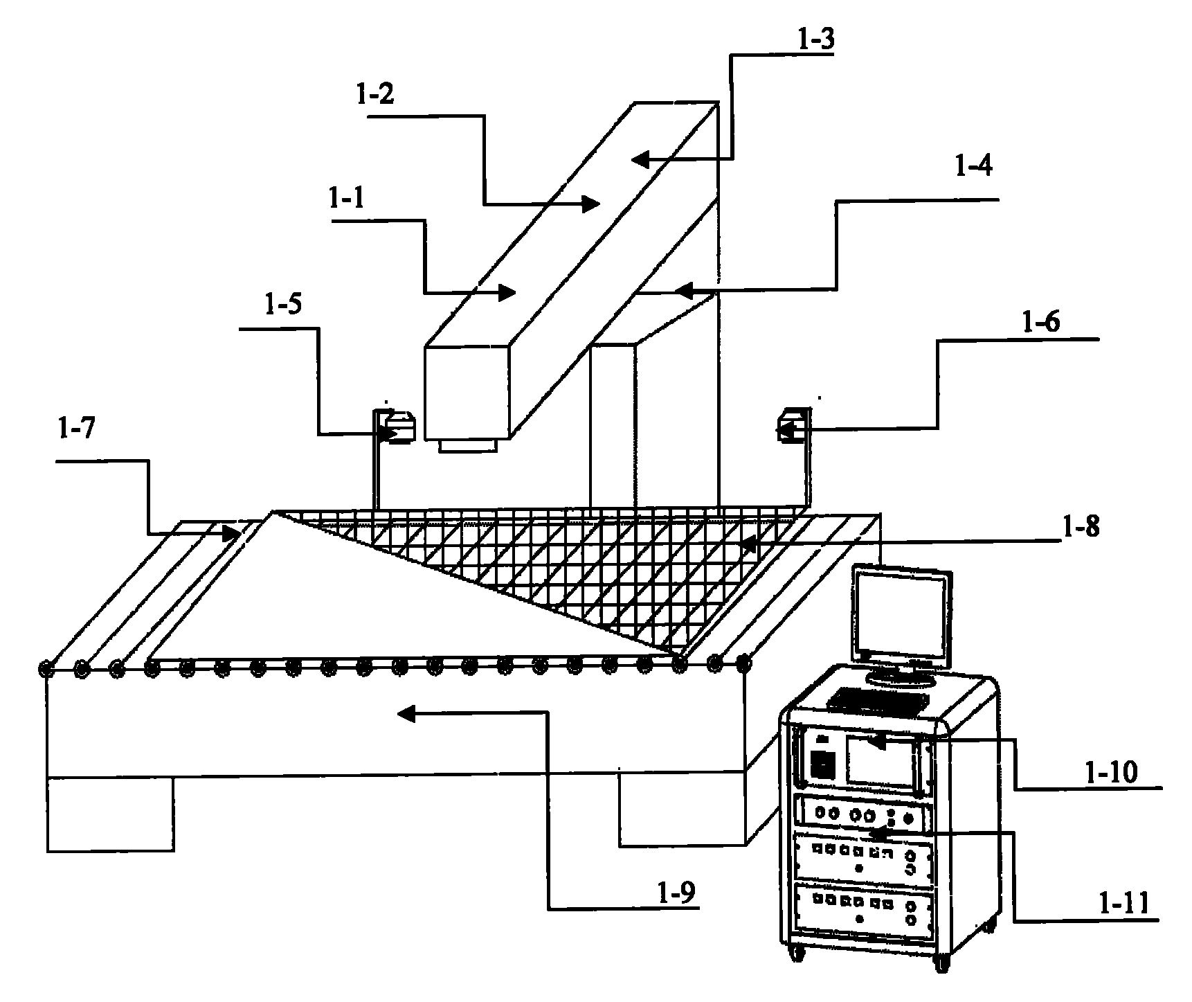
Figure 1 
Figure 2 
Figure 3
Abstract
Description
Technical field
[0001] The invention relates to a laser marking equipment, in particular to a device for marking and marking thin-film solar cells. Background technique
[0002] At present, laser processing technology has been widely used in the production of amorphous silicon thin-film solar cells to realize the scribing and dotting of solar cells. The Chinese patent number ZL200710072812 solar cell laser marking equipment uses an XY galvanometer and a dedicated large-format X---Y worktable to realize the marking of the cells. Although this method has a certain improvement in marking speed compared with the original, and can mark large-format and special-patterned solar thin-film batteries, it still requires the substrate of the solar thin-film battery to move on a mobile workbench, and the speed is bound to be affected by the large-format The movement speed of the worktable is limited, and due to the vibration of the worktable during the movement process, uneven and unstable p...