Novel apparatus used for film engraving and dotting of thin-film solar cell

A technology of solar cells and new devices, applied in circuits, electrical components, laser welding equipment, etc., can solve the problems of repeated lines, inconsistent marking quality, repeated points, etc., to achieve automatic and accurate alignment, avoid marking errors, and achieve counterpoint effect

Inactive Publication Date: 2009-05-13
WUHAN LINGYUN PHOTOELECTRONICS SYST
View PDF1 Cites 30 Cited by
  • Summary
  • Abstract
  • Description
  • Claims
  • Application Information

AI Technical Summary

Problems solved by technology

Although this method has a certain improvement in marking speed compared with the original one, and can mark solar thin film cells with large format and special graphics, it still needs the substrate of solar thin film cells to move on the mobile workbench, and the speed is bound to be limited by the large format. The movement speed of the worktable is limited, and due to the vibration of the worktable during the movement process, the engraved film and the dotted line will be uneven and unstable, and the large-format precision X---Y mobile workbench is in the whole marking equipment The cost will account for more than half of the cost, resulting in a high cost of marking a single substrate. In the large-format working state, the marking m

Method used


Image

  • Novel apparatus used for film engraving and dotting of thin-film solar cell
  • Novel apparatus used for film engraving and dotting of thin-film solar cell

Examples


Embodiment 1

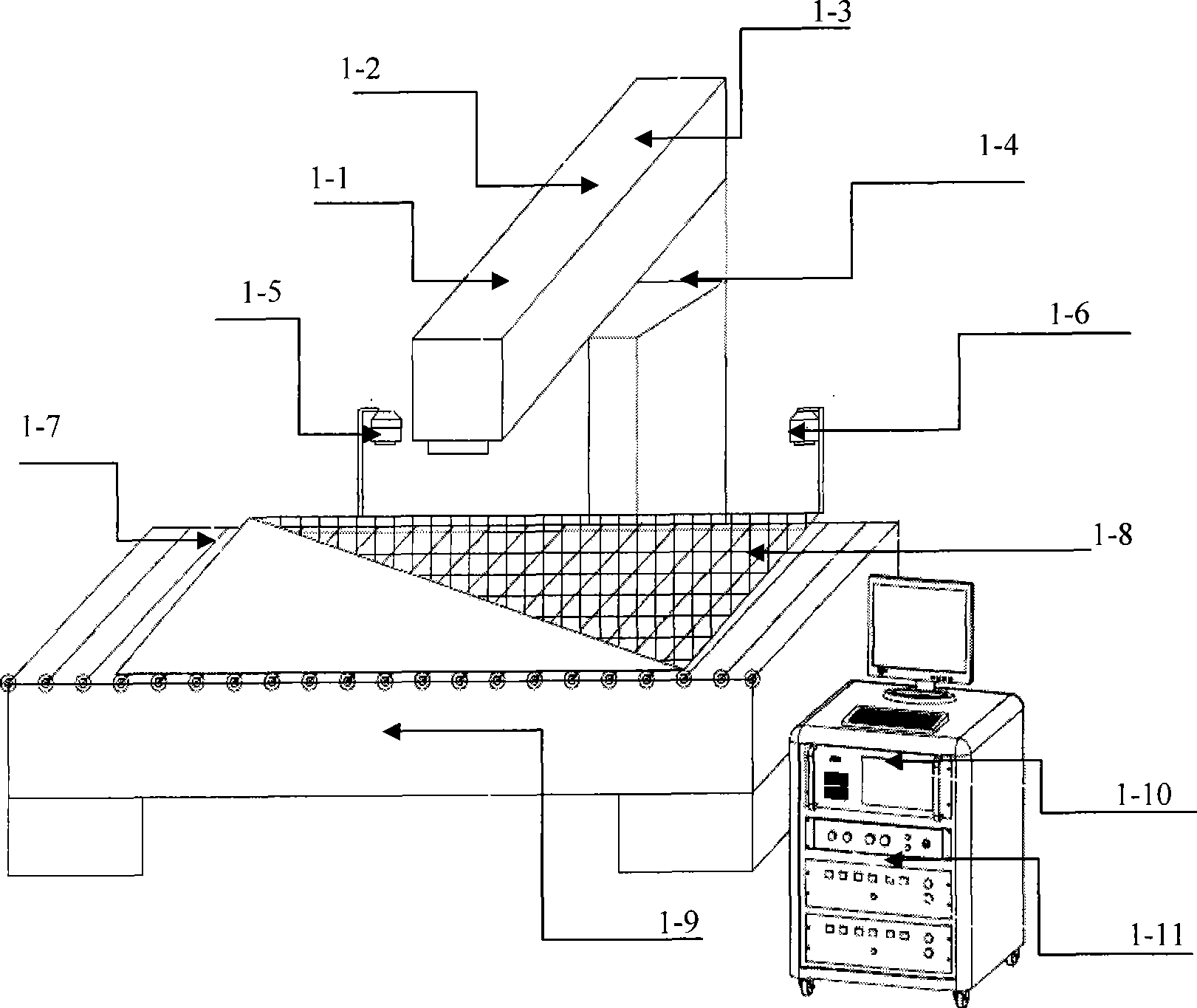
[0033] Embodiment 1: Marking and producing thin-film solar cell substrates 1-8 with a length of 20 mm and a width of 10 mm as a rectangular block with a unit cell spacing of 1000 mm×1000×0.8 mm. Fabrication of the front electrode pattern: Place the ITO, ZNO or SNO2 transparent conductive film with a size of 1000mm×1000×0.8mm facing up on the figure 1 In the No. 1 marking area, the auxiliary roller feeding mechanism 1-7 on the mirror table 1-9 moves forward slowly under the control of the industrial computer 1-10. We use the In- The Sight5400 series vision sensor is deployed in this application environment as an independent vision system, and its vision software implements the automatic alignment function. The data analysis of the industrial computer 1-10 enables the laser generator 1-3 to accurately position the object. In a standard application environment, the overall response time of image evaluation is about 180 milliseconds, and its resolution is 640*480 pixel units.

[...

Embodiment 2

[0038] Embodiment 2: Marking and producing a thin-film solar cell substrate with a rectangular block with a length of 30 mm and a width of 10 mm and an overall size of 1200 mm×800×0.6 mm.

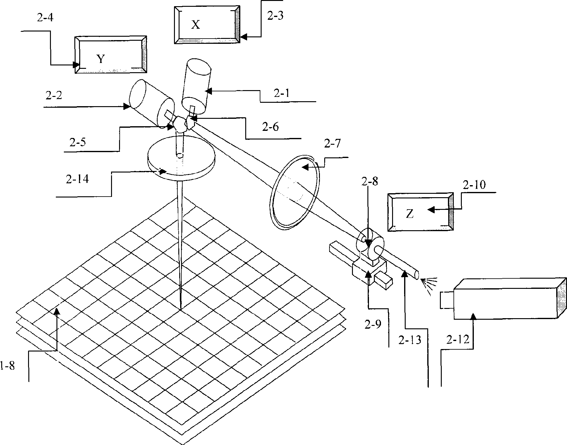
[0039] Front electrode graphics production: place the transparent conductive film with a size of 1200mm×800×0.6mm facing down on the figure 1 In the No. 1 marking area, the auxiliary roller feeding mechanism 1-7 on the mirror table 1-9 is slowly moving forward under the control of the industrial computer 1-10, the same as the above steps, after the solar thin film substrate reaches the designated position, The automatic camera positioning subsystem 1-6 realizes searching for the positioning line on the surface of the transparent conductive film, and controls and stops the feeding mechanism 1-7 immediately after finding it. After positioning, we use a digital laser sensor to detect the current height from the surface of the thin-film solar panel to the vibrating lens, and directly modify the...


PUM

PropertyMeasurementUnit
Apertureaaaaaaaaaa

Abstract

The invention relates to a new device used for scribing and pointing of a thin film solar cell. The device comprises a laser, a support pedestal, an automatic focusing control subsystem, an automatic photographing positioning subsystem, an optical platform, an industrial control computer, a power supply and a dynamic galvanometric scanning subsystem. The device is characterized in that a feeding mechanism is arranged on the optical platform, wherein, the support pedestal, the automatic focusing control subsystem and the automatic photographing positioning subsystem are arranged on one side surface of the optical platform. An X-Y-axis galvanometric scanning unit, a Z-axis front focusing unit and the laser are arranged in a beam of the support pedestal. The industrial control computer is respectively connected with the laser, the X-Y-axis galvanometric scanning unit, the Z-axis front focusing unit and the power supply by cables. The invention has the advantages of simple structure, standard process, low production cost, easy mass production, wide scanning range, small focusing spot, good consistency, automatic and accurate positioning, high working efficiency, and the like, thereby being capable of being widely applied in scribing, pointing and other production fields of amorphous silicon solar cells.

Description

technical field [0001] The invention relates to a laser marking device, in particular to a new device for film marking and dotting of thin-film solar cells. Background technique [0002] At present, laser processing technology has been widely used in the production process of amorphous silicon thin-film solar cells to achieve film engraving and dotting of cells. China Patent No. ZL200710072812 solar cell laser marking equipment uses an XY vibrating mirror and a special large-format X---Y table to mark cells. Although this method has a certain improvement in marking speed compared with the original one, and can mark solar thin film cells with large format and special graphics, it still needs the substrate of solar thin film cells to move on the mobile workbench, and the speed is bound to be limited by the large format. The movement speed of the worktable is limited, and due to the vibration of the worktable during the movement process, the engraved film and the dotted line w...

Claims


Application Information

Patent Timeline
IPC IPC(8): H01L31/18B23K26/00B23K26/04B23K26/362
CPCY02P70/50
Inventor 王锋吴华
Owner WUHAN LINGYUN PHOTOELECTRONICS SYST
Why Eureka
Try Eureka