Sealing arrangement

A sealing device and sealing lip technology, applied in the direction of engine sealing, engine components, mechanical equipment, etc., can solve problems such as difficult adjustment and leakage

Inactive Publication Date: 2011-11-09
ANDRITZ AG
View PDF4 Cites 0 Cited by
  • Summary
  • Abstract
  • Description
  • Claims
  • Application Information

AI Technical Summary

Problems solved by technology

The disadvantage of seal boxes is that they are always somewhat leaky and difficult to adjust to compromise between sealing and leaking, and there is not much resistance to the rotation of the shaft that needs to lubricate and cool the seals

Method used


Image

  • Sealing arrangement
  • Sealing arrangement
  • Sealing arrangement

Examples


Embodiment Construction

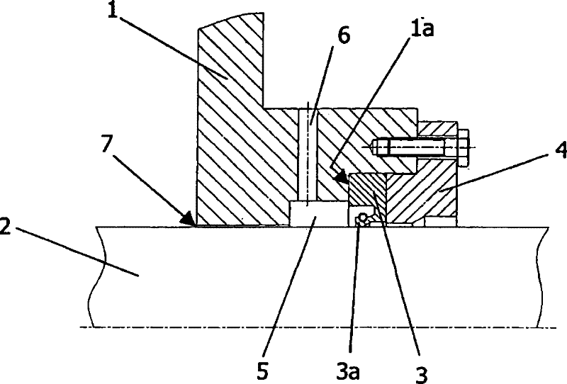
[0023] figure 1 A sectional view is shown of a housing 1 with a sealing device according to the invention intended to seal the introduction of a rotating shaft 2 through an opening in the housing 1 . In the very simple example shown, the sealing arrangement comprises a single-lip seal 3 with a sealing lip 3a facing the area normally under higher pressure.

[0024] The lip seal 3 is placed on the protrusion 1 a of the opening in the housing 1 and is pressed against the protrusion 1 a by the pressure ring 4 . A circumferential grooved area 5 is formed between the protrusion 1 a and a part of the opening of the housing 1 surrounding the shaft 2 with a narrow gap. A hole 6 in the housing 1 leads to this area 5 on said side of the lip seal 3 which normally faces the higher pressure, so that the area 5 can be connected to a pressure source. The medium used for pressurization is preferably a medium already used in the process or a medium present on the side which is usually at a hi...


PUM


Abstract

A sealing arrangement for the sealed leadthrough of rotating shafts (2) through housing bores of housings (1) comprises at least one lip seal (3, 8, 14, 15) with a sealing lip which faces toward the region with normally higher pressure. In order to significantly widen the field of use of sealing arrangements with lip seals, and to thereby obtain, even in the event of relatively high pressures andpressure fluctuations, the advantages of said sealing arrangements with lip seals with regard to greater economic viability, better durability even in the event of pressure peaks, simpler installation and simpler servicing, the lip seal (3, 8, 14, 15) is acted on, on the side (5) which faces toward the region with the higher pressure, with a constant pressure which is higher than the highest pressure occurring within the housing (1), and a gap (7, 10) which throttles the outflow is provided between said region and the housing interior.

Description

technical field [0001] The invention relates to a sealing device for sealing a shaft introduced through a borehole in a housing, said sealing device comprising at least one lip seal with a sealing lip. Background technique [0002] Lip seals are used in many applications where a rotating shaft enters or exits a housing in a sealing arrangement, for example on propeller drive shafts in marine engines as disclosed in EP335368A1. Here, in the sealing ring according to EP1055849A2, the sealing lip faces the region which is generally under low pressure. In the latter case, measurements are taken to maintain the same pressure on both sides of the sealing lip, however, this pressure cannot be kept at a constant level. A lip seal which is not under pressure at all is known, for example, from DE4039666A1. [0003] Furthermore, EP 0480693A1 describes a shaft seal between chambers with different pressures, eg in a pump or turbine, mixing of fluids on either side should be avoided. T...

Claims


Application Information

Patent Timeline
Patent Type & Authority Patents(China)
IPC IPC(8): F16J15/00F16J15/40F16J15/54
CPCF16J15/406F16J15/54F16J15/004F16J15/006
Inventor 托马斯·巴希霍弗纳斯特凡·霍纳
Owner ANDRITZ AG
Why Eureka
Try Eureka