Mechanism for shearing steel bar straightening and shearing machine

A shearing mechanism and cutting machine technology, applied in the field of shearing mechanism, can solve the problems of increased use cost, inability to cut steel bars, waste of raw materials, etc., and achieve the effect of prolonging the service life and avoiding repeated friction

Inactive Publication Date: 2009-05-20
何川
View PDF0 Cites 12 Cited by
  • Summary
  • Abstract
  • Description
  • Claims
  • Application Information

AI Technical Summary

Problems solved by technology

Because the elimination of the movement consistency of the two shearing gears after cutting the steel bar is controlled by the wheel disc and the brake ring installed at the other end of the gear shaft, and the wheel disc brakes in the inner hole of the brake ring by the friction between the two circumferential surfaces. , after cutting the steel bar each time, the position where the shearing blade stops is not constant. Therefore, the unsolvable defect of this kind of shearing mechanism is that there is always an error of 20-30 (mm) in the cutting length, and the raw material is wasted.
The other is a hydraulic shearing shearing mechanism. The main defect of this mechanism is that it cannot cut steel bars with a length shorter than 500 (mm), and the mechanism will cost 2000-4000 yuan to add hydraulic oil once. Increased cost of use

Method used


Image

  • Mechanism for shearing steel bar straightening and shearing machine
  • Mechanism for shearing steel bar straightening and shearing machine

Examples


specific Embodiment approach

[0023] The specific implementation, non-limiting examples are as follows:

Embodiment

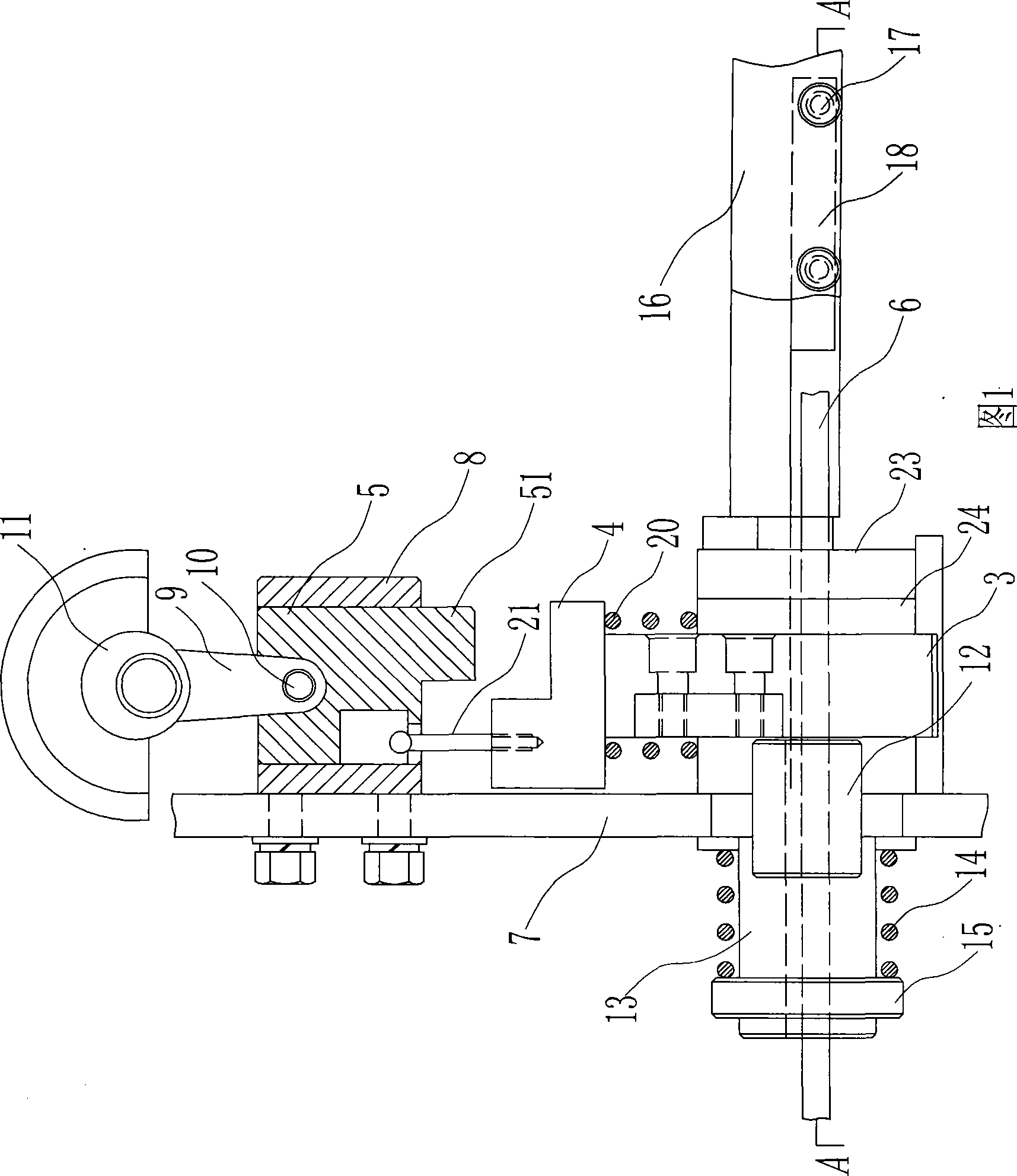
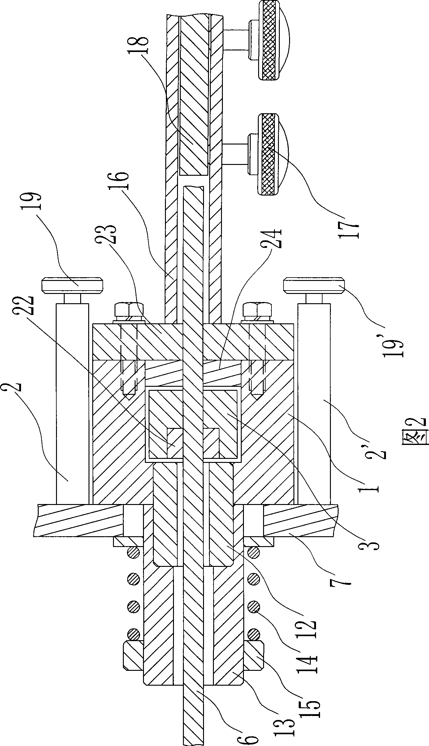
[0024] Embodiment: As shown in Figures 1 and 2, the shearing mechanism used in the steel bar straightening and cutting machine described in this embodiment, the shearing seat 1 is arranged between two parallel groove plates 2, 2' of the frame to Ensure that it can move in a straight line from left to right. The cross-section of the shearing seat is in the shape of a "mouth". Threaded connection (of course, key connection or other forms of fixed connection) is at the lower end of the bearing seat 4, and the bearing seat is "L" shaped, and the punch block 51 at the lower end of the punching seat 5 in the non-shearing state cannot impact the bearing seat 4 , in the shearing state, that is, when the receiving seat 4 moves to the right for a certain distance, the punching block 51 can impact the high end of the receiving seat to drive the moving knife body 3 to cut off the steel bar 6. As shown in Figure 1, the punching seat 5 is located at Fixed in the guide seat 8 on the wallboar...


PUM


Abstract

The invention discloses a shearing mechanism for a reinforcing steel adjusting cutter. The mechanism is provided with a dimensioning block and a positioning baffle plate which can limit a shearing pedestal. A reinforcing steel bar to be sheared is precisely cut at the required length each time by a shearing opening which is formed by a fixed cutter body and a movable cutter body in the shearing pedestal, so that the blanking length of the reinforcing steel bar is precise and errorless, and raw materials can be greatly saved; simultaneously, due to arrangement of offsetting pressure springs and lifting rods, the movable cutter body can be guaranteed to stably reset in time, so as to perform next shearing action, the consistency of the shearing motion is guaranteed. The shearing mechanism for the reinforcing steel adjusting cutter has low cost, and can guarantee high-efficiency and continuous operation of the machine; and the length of the sheared reinforcing steel bar is precise.

Description

Technical field: [0001] The invention relates to a shearing mechanism, in particular to a shearing mechanism in a steel bar straightening and cutting machine. Background technique: [0002] There are two types of shearing mechanisms for steel bar straightening and cutting machines currently on the market: one is the gear cutting type, and this mechanism is equipped with a shearing blade on two mutually meshing gears. When the blade is in the corresponding position, cut the straightened steel bar. Because the elimination of the movement consistency of the two shearing gears after cutting the steel bar is controlled by the wheel disc and the brake ring installed at the other end of the gear shaft, and the wheel disc brakes in the inner hole of the brake ring by the friction between the two circumferential surfaces. , after cutting the steel bar each time, the position where the shearing blade stops is not constant. Therefore, the unsolvable defect of this kind of shearing mec...

Claims


Application Information

Patent Timeline
Patent Type & Authority Applications(China)
IPC IPC(8): B21F11/00B21F1/02
Inventor 何川
Owner 何川
Why Eureka
Try Eureka