Shearing force measurement bridge circuit in bending-twisting combined test apparatus

A combination of test device and bending torsion technology, applied in the direction of measuring force, measuring device, instrument, etc., can solve the problems of large measurement error and bending normal stress that cannot be eliminated, so as to improve measurement accuracy, enrich experimental teaching content, and increase thinking and fun effects

Inactive Publication Date: 2009-07-22
HEFEI UNIV OF TECH
View PDF0 Cites 5 Cited by
  • Summary
  • Abstract
  • Description
  • Claims
  • Application Information

AI Technical Summary

Problems solved by technology

When measuring with a 45°-3 right-angle strain rosette, since the center of the sensitive grid does not coincide with the measuring point, when using the full bridge to measure the bending shear stress, only the torsional shear stress can be offset, and the additional bending normal stress cannot be eliminated, thus lead to large measurement errors due to Figure 5 It can also be seen that, in addition to the influence of the lateral effect and the paste orientation, the main error of the shear force measurement is caused by the inconsistency between the stress state at the center of the strain rosette and the pure shear stress state of the measured point

Method used


Image

  • Shearing force measurement bridge circuit in bending-twisting combined test apparatus
  • Shearing force measurement bridge circuit in bending-twisting combined test apparatus
  • Shearing force measurement bridge circuit in bending-twisting combined test apparatus

Examples


Embodiment Construction

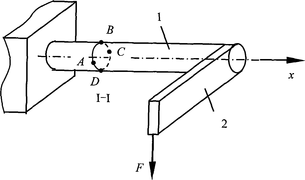
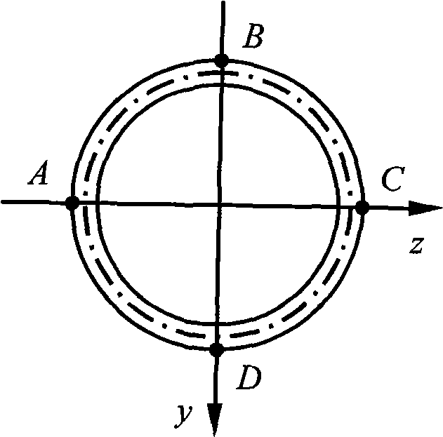
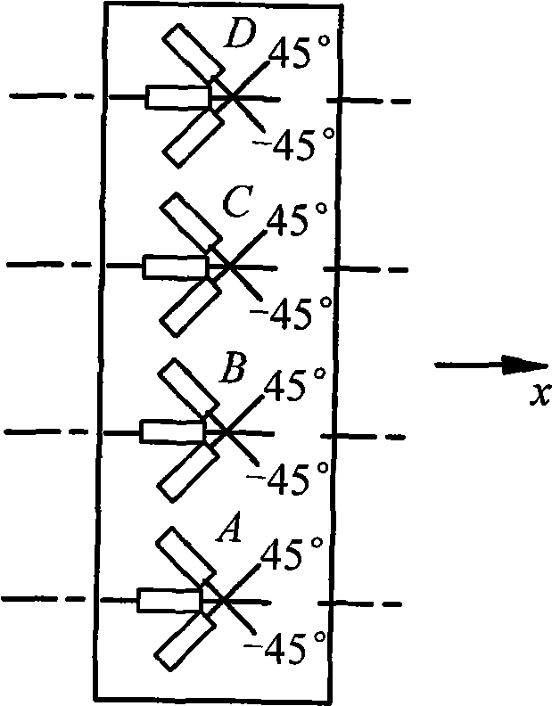
[0038] see figure 1 , figure 2 and Figure 6 In this embodiment, according to the rosette arrangement in the prior art, the rosette at point A is rotated 180° and pasted. As shown in the figure, the same as the prior art, the aluminum alloy cylinder cantilever bellcrank structure is adopted, which is composed of an aluminum alloy cylinder cantilever 1 and a bellcrank 2 at an angle of 90° to it. On the outer circumference of the cross-section, arrange four 45°-3 right-angle rosettes in the order of rosette A, rosette B, rosette C, and rosette D at intervals of 90°. The difference from the prior art is that in the axial direction of the cylindrical cantilever 1, the rosette B, the rosette C and the rosette D have the same orientation, and the rosette A is opposite to the other three rosettes, and the measuring point The position of the circle is the center of symmetry.

[0039] The application of the bending-torsion combined test device in this embodiment on the measurement...


PUM


Abstract

The invention relates to a shearing force measuring bridge circuit in a crankle combined test device. The device consists of an aluminum alloy cylinder cantilever and a crank which is in an angle of 90 degrees with the cylinder cantilever; the outer circumference of the measured cross section of the aluminum alloy cylindrical cantilever is provided with four 45-degree 3-right angle strain rosettes at an interval of a 90-degree interval according to an order of a strain rosette A, a strain rosette B, a strain rosette C and a strain rosette D; and the device is characterized in that the orientations of the strain rosette B, the strain rosette C and the strain rosette D are the same along the axis direction of the cylinder cantilever, the orientation of the strain rosette A is opposite to the orientations of the other strain rosettes, and a circumference position where a measuring point is located is taken as the symmetric center. The shearing force measuring bridge circuit can obtain higher measuring precision on flexural moment and torque, can effectively measure shearing force, so as to add new teaching experiment content, and can provide a model for internal force measurement of similar components in engineering structures.

Description

[0001] This application is a divisional application with the application number "200610088185.1", the filing date of "June 30, 2006", and the title of the invention "Bending-Torsion Combined Test Device and Its Application in Internal Force Measurement". technical field [0002] The invention relates to a bending-torsion combined test device, more specifically a shear force measuring bridge in the bending-torsional combined test device. Background technique [0003] Resistance strain measurement technology is one of the main methods for stress analysis of engineering structure tests, and is widely used in various engineering and technical fields such as machinery, civil engineering, and aerospace. Learning the principle of resistance strain measurement, mastering its measurement methods and techniques, and being able to apply them proficiently is a basic experimental skill that students in engineering colleges, especially those majoring in engineering technology, must master....

Claims


Application Information

Patent Timeline
Patent Type & Authority Applications(China)
IPC IPC(8): G01L1/22G09B25/04
Inventor 李昊刘一华詹春晓王美芹吴枝根
Owner HEFEI UNIV OF TECH
Why Eureka
Try Eureka