Filter element

A technology of filter element and coarse filtration, which is applied in the direction of fixed filter element filter, filtration separation, chemical instrument and method, etc., can solve the problems of increasing filter element cost, time-consuming and expensive, complicated production of star-shaped folded filter element, etc., and achieve the improvement of filtration performance , simple arrangement, and the effect of increasing the adsorption capacity

Inactive Publication Date: 2009-05-27
IBS菲尔特兰塑料金属产品有限责任公司
View PDF0 Cites 11 Cited by
  • Summary
  • Abstract
  • Description
  • Claims
  • Application Information

AI Technical Summary

Problems solved by technology

The production of star-shaped pleated filter elements is more complicated, and the star-shaped pleats are realized by a pleating system, which is time-consuming and expensive
Also, due to the major pressure differentials, the filter media must be provided with support grids to prevent collapse of the star folds, thus further increasing the cost of this element

Method used


Image

  • Filter element
  • Filter element
  • Filter element

Examples


Embodiment Construction

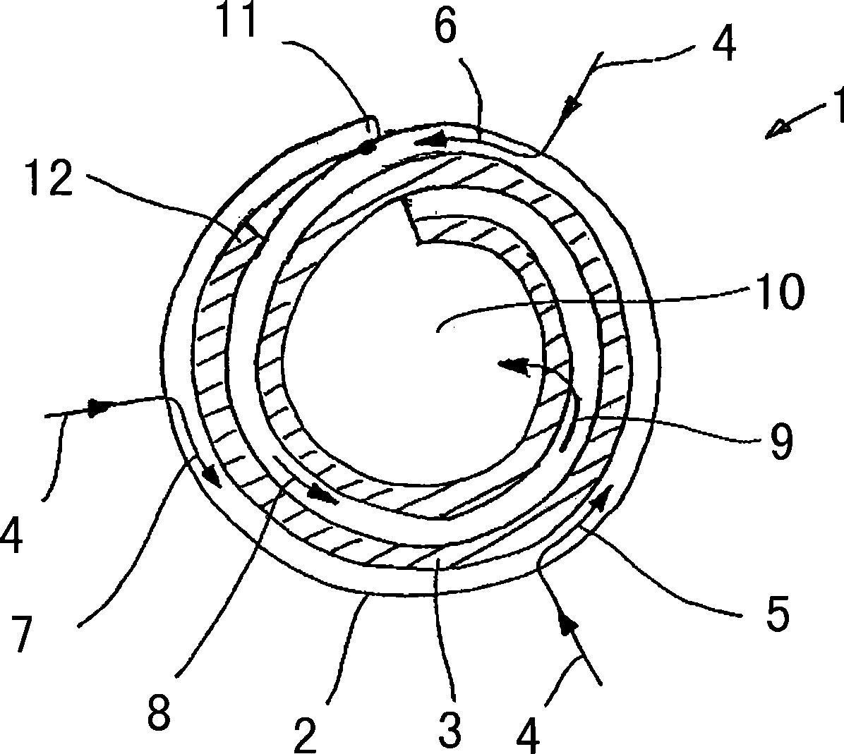
[0021] figure 1 shows a filter insert 1 consisting of a coarse filter medium 2 as an outer layer and a fine filter medium 3 as an inner layer. The two layers are stacked on top of each other and wound together in a helical fashion. in such as figure 1 In the shown embodiment, a space is provided between the two filter media, while the two layers are in contact with each other, so that a compact structure is obtained. The filtered liquid encounters the surrounding surface of the outer layer (see arrow 4) in a vertical manner and penetrates said outer layer. Filtration starts here and the liquid encounters the fine filter medium 3 after penetrating the coarse filter medium 2 . Part of the liquid will permeate into the fine filter medium 3, while the other part advances along the coarse filter medium 2 in a helical manner in the direction of the geometric center of the filter element 1 (see arrows 5 to 8). After passing through the coarse filter medium 2 for a certain path len...


PUM


Abstract

The invention relates to a filter element for filtering fluid for a motor or gearing, comprising a first filter medium which is arranged in a cylindrical way, with the fluid impinging in a perpendicular way on the circumferential surface of the first medium for filtering in an associated filter apparatus, then penetrating and passing through the same. The filter element comprises a second filter medium with a filter density differing from the first filter medium, the first filter medium and the second filter medium being stacked upon each other as filter layers and being jointly wound in a spiral manner. A desired purity of the fluid can thus be achieved more quickly than in filter elements which exclusively allow a radial passage of the fluid through the filter elements. The spiral configuration also achieves a higher dirt absorption capacity.

Description

technical field [0001] The invention relates to a filter element for filtering liquids for electric motors or transmissions, the filter element having a first filter medium mounted in a cylindrical manner. The invention further relates to a filter device using such a filter element. Background technique [0002] A pressure filter may be used in a liquid bypass to filter fluid in the motor or transmission. To avoid endangering the cooling output of the motor or transmission, it is appropriate to always allow sufficient fluid to flow through the pressure filter or associated element. . In the case of a uniform flow rate, this causes an increase in the differential pressure between the liquid inlet and the liquid outlet of the filter elements whose liquid permeability is reduced due to the adsorbed filter particles. Once the differential pressure exceeds a predetermined value, the liquid is typically directed through a bypass valve rather than through and filtered at the filt...

Claims


Application Information

Patent Timeline
Patent Type & Authority Applications(China)
IPC IPC(8): B01D29/15
CPCB01D35/147B01D29/216B01D35/00B01D39/00
Inventor 沃尔夫冈·施陶斯贝格丹尼尔·贝尔纳茨
Owner IBS菲尔特兰塑料金属产品有限责任公司
Why Eureka
Try Eureka