Battery powered shuttle car

a shuttle car and battery technology, applied in the field of mining vehicles, can solve the problems of no longer being able to travel independently in the shortest possible distance between, no longer being able to travel independently, and the shuttle car cannot travel in the shortest possible distance, etc., and achieves the effects of uniform tire loading, low vulnerability to damage of the battery, and simple and effectiv

Inactive Publication Date: 2010-08-10
PHILLIPS MACHINE SERVICE
View PDF30 Cites 22 Cited by
  • Summary
  • Abstract
  • Description
  • Claims
  • Application Information

AI Technical Summary

Benefits of technology

[0014]According to the present invention a new type of battery powered shuttle car is provided which avoids the problems of the original battery powered shuttle cars while retaining their advantages, which is significantly superior to the cable reel shuttle cars and conventional battery powered haulage compartment articulated vehicles, which achieves the objectives set forth above in a simple and effective manner. According to the present invention a battery powered shuttle car is provided that has batteries mounted with respect to the vehicle so that there is substantially uniform tire loading, little vulnerability to damage of the batteries by mining equipment, solid state electronic motor control that provides infinitely variable control while conserving battery energy, and simple and effective battery removal and replacement. The shuttle car according to the invention also utilizes tire technology that can handle the combined load of the machine, payload, as well as a lead acid battery of sufficient capacity to make cable-less battery powered functionality viable. That is, the shuttle car according to the invention may readily incorporate batteries having an amp hour capacity of at least 500, e.g. about 500-2500, amp hours.

Problems solved by technology

It soon became apparent, however, that a battery, the size and capacity of which had been dictated by the constraints of the vehicle configuration, mining dimensions, and other technology of the time, coupled with the realities of weight and balance, was an impractical energy source in production mining environment.
As a consequence, however, a shuttle car can no longer travel independently in the shortest possible distance between the production face and the dump point.
Also, no longer can more than one car travel the same route without interference from other cars, and no longer can the mining supervisor extend the haulage to meet other needs without additional complications, such as the splicing-in of additional cable which cannot be accommodated on the cable reel.
While such a design is optimal for the incorporation of large 1500 amp hour or greater batteries, there are a number of operational disadvantages for such a vehicle.
The articulated configuration of this type of car also makes it difficult to provide all-wheel drive.
Two wheel drive produces traction problems in the wet, soft bottoms and gradients that characterize many mining operations.
The traction problem is further exacerbated by the uneven distribution of weight carried by the tires, especially when the shuttle car is traveling in the unloaded portion of the cycle.
The consistently high loading of the tires on the battery / traction end of the shuttle car also shortens the life of these tires, so much so that some manufacturers have even resorted to solid tires constructed of synthetic, non-rubber materials with attendant reductions in tractive capabilities as an undesirable trade-off.
For many purposes, however, such an elevating structure is not useful, and with the particular battery powered shuttle car of this invention, it can be much more desirable to provide a fixed height discharge at the unloading end.
It is difficult to position the operator's compartment safely and effectively (so that the operator can easily operate the shuttle car), while not interfering with the coal or other mined material transport function of the conveyor, and still allow the operator to see when the shuttle car is “full” of material, so that it should be operated to go to a discharge location.

Method used


Image

  • Battery powered shuttle car
  • Battery powered shuttle car
  • Battery powered shuttle car

Examples


Embodiment Construction

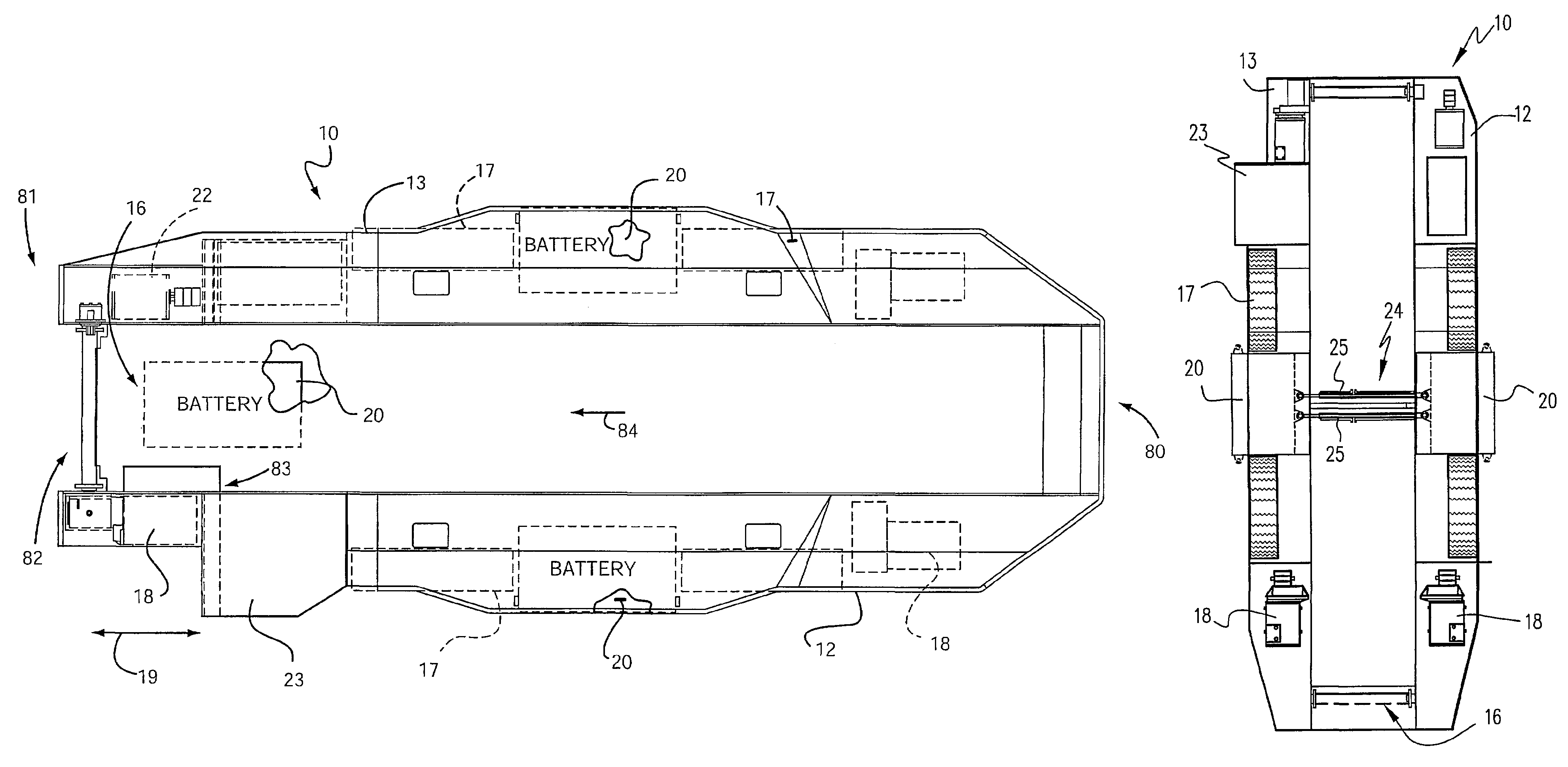
[0041]The particular location of the batteries with respect to the shuttle car, and the motors for powering the wheels of the shuttle car, and the operator's compartment, as well as the quantity of batteries, will depend upon the maximum height restrictions for the coal seam, geological conditions, or other operating environment and the load carrying capacity of the shuttle car. Some particular advantageous configurations in that regard are illustrated in FIGS. 1, 2, 4 and 8-12 of the drawings.

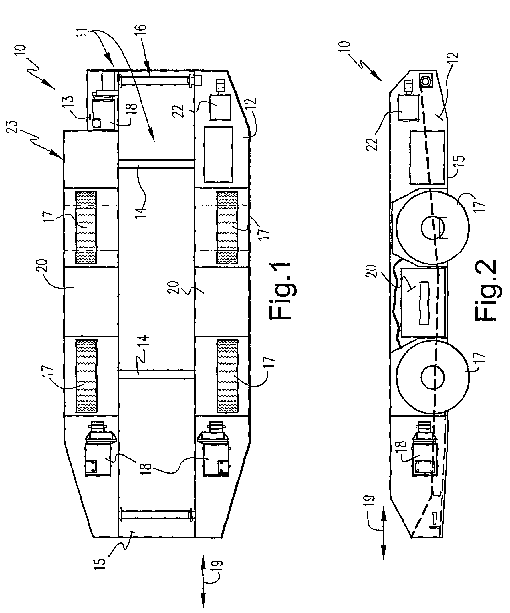
[0042]Particularly with respect to the FIGS. 1 and 2 embodiment, a first embodiment of the battery powered shuttle car 10 is illustrated comprising a frame 11 that includes first and second side portions 12, 13, and any suitable cross portions (shown schematically at 14 in FIG. 1, but alternatively provided by a frame portion 15), and a conveyor of conventional configuration—only shown schematically by reference numeral 16 in FIG. 1, but shown, in one embodiment, in more detail in FIG. 13—betw...


PUM


Abstract

A battery powered shuttle car (10) incorporates features and components that facilitate use and operation and effect efficient application in a mining environment. The shuttle car (10) incorporates at least one battery (20) that is secured to the vehicle frame (11) between one of a left front wheel (17) and a left rear wheel (17) or the right front wheel (17) and the right rear wheel (17). A battery change-over mechanism (51) facilitates battery replacement. Additionally, the shuttle car (10) may be provided with an integral discharge end (81) having a substantially fixed height (82). A full load indicator mechanism (83) provides an indication when the conveyor (16) is substantially full to maximize use and operation of the shuttle car (10).

Description

[0001]This application is the U.S. national phase of International Application No. PCT / US01 / 28369 filed 13 Sep. 2001 which designated the U.S. and claims priority to U.S. Provisional Patent Application Ser. No. 60 / 230,933 filed 13 Sep. 2000, and U.S. Provisional Patent Application Ser. No. 60 / 238,016 filed 6 Oct. 2000 the entire contents of each of which are hereby incorporated by reference.STATEMENT REGARDING FEDERALLY SPONSORED RESEARCH OR DEVELOPMENT[0002](NOT APPLICABLE)BACKGROUND OF THE INVENTION[0003]The present invention relates to mining vehicles and, more particularly, to a battery powered mining shuttle car.[0004]One function that always must be performed during mining is to transport mined material from the point of mining to a point of discharge, such as into a feeder device which ultimately transports the mined material to the mine mouth. Starting at least as early as the 1940's (e.g., see U.S. Pat. Nos. 2,192,650; 2,588,341 and 3,370,667), this was accomplished utilizi...

Claims


Application Information

Patent Timeline
Patent Type & Authority Patents(United States)
IPC IPC(8): B60K1/04B60R16/04B60P1/00G01F23/00B60K17/356E21F13/02
CPCB60L3/04B60L11/1805B60L11/1822B60L11/1877B60L15/38E21F13/025B60L3/0046B60K17/356B60L2200/26B60L2200/44B60L2260/28B60L2260/32Y02T10/7005Y02T10/705Y02T10/7072Y02T90/124Y02T90/14B60L50/52B60L50/66B60L53/80B60L58/18Y02P90/60Y02T10/70Y02T90/12
Inventor ALLEN, CLAUDE R.CUSHMAN, THOMAS S.HICKOK, JIMMY A.MCWHORTER, PURNAL L.
Owner PHILLIPS MACHINE SERVICE
Why Eureka
Try Eureka