Self-adapting stabilized contact electric resistance measuring apparatus

A resistance measurement and self-adaptive technology, applied in measurement devices, measurement of electrical variables, measurement of resistance/reactance/impedance, etc., can solve problems such as poor measurement contact, reduce the difficulty of preparation and processing, avoid point contact, and ensure uniform distribution. Effect

Inactive Publication Date: 2009-05-27
BEIJING INSPECT TECH
View PDF0 Cites 7 Cited by
  • Summary
  • Abstract
  • Description
  • Claims
  • Application Information

AI Technical Summary

Problems solved by technology

[0003] The object of the present invention is to provide a resistance measuring device with self-adaptive and stable contact, to solve the problem of poor contact measurement in the above-mentioned existence

Method used


Image

  • Self-adapting stabilized contact electric resistance measuring apparatus
  • Self-adapting stabilized contact electric resistance measuring apparatus
  • Self-adapting stabilized contact electric resistance measuring apparatus

Examples


Embodiment Construction

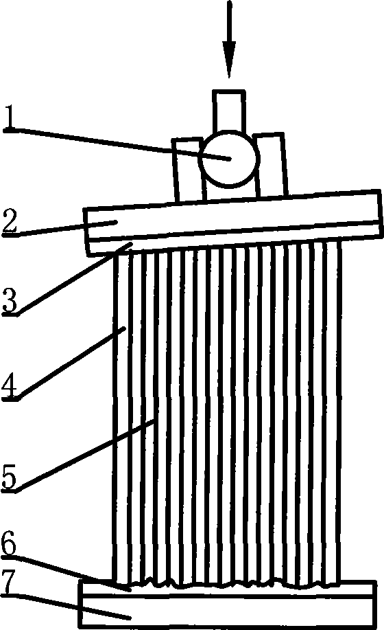
[0022] The measuring device of the present invention is illustrated by measuring the resistivity of a carbon product for aluminum. The sample is a cylinder with a diameter of 50 mm and a length of 130 mm.

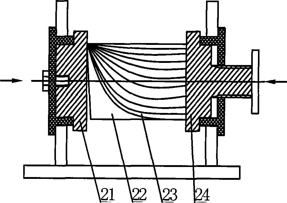
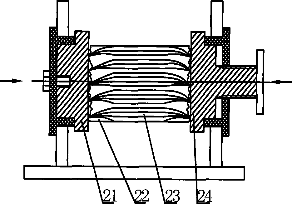
[0023] The measurement is carried out using the measuring device of the present invention. During operation, the upper and lower conductive substrates are in contact with the two end surfaces of the sample, and the pressure drop of the two cross-sections at a certain distance is measured after the current is turned on, and the resistivity of the sample is calculated. image 3 , 4 Shown is a schematic diagram of the structure and operation of an adaptive and stable contact resistance measuring device of the present invention. The device of the present invention includes an upper conductive substrate 2 and a lower conductive substrate 7, and a universal joint is installed on the top of the upper conductive substrate 2. Axis 1. The working surfaces of the upper conductive s...


PUM


Abstract

A self-adapting stably contacted resistance measurement device comprising an upper conducting substrate and a lower conducting substrate is characterized in that the top of the upper conducting substrate is equipped with a universal-joint spindle. Working surfaces of the upper conducting substrate and the lower conducting substrate are both coated with a soft metal clad which can be fixed on the working surfaces of the upper conducting substrate and the lower conducting substrate by nuts. The device can ensure full contact between the conducting substrates and the end face of a sample and uniform distribution of stable contact resistance and current when passing through the sample and realize accurate measurement. Therefore, the device is applicable to the measurement devices for measuring the resistance and the specific resistance of heterogeneous material.

Description

technical field [0001] The invention relates to a measuring device for measuring resistance and resistivity of heterogeneous materials, in particular to a resistance measuring device for self-adaptive and stable contact. Background technique [0002] In the current device used to measure the resistivity of heterogeneous materials, the contact surfaces between the metal conductive plates at both ends and the tested sample are hard contacts whose direction cannot be adjusted. If the two ends of the sample are not flat or the flatness of the end face cannot meet the requirements, the contact between the conductive plate and the end face of the sample will be partial contact or point contact, which not only causes the contact resistance of the contact surface to be uncertain, but also for non-uniform When the current passes through the cross-section of the sample, the solid material will cause the bias current of the current, which will cause a large error in the measurement res...

Claims


Application Information

Patent Timeline
Patent Type & Authority Applications(China)
IPC IPC(8): G01R27/08
Inventor 李红梅
Owner BEIJING INSPECT TECH
Why Eureka
Try Eureka