LCD module and method for measuring contact electric impedance between circuit boards therein

A liquid crystal display module, contact impedance technology, applied in the measurement of resistance/reactance/impedance, measurement device, measurement of electrical variables, etc., can solve the problems of labor-intensive cost, dependence on labor, inaccurate judgment results, etc., to improve reliability degree of effect

Inactive Publication Date: 2009-05-27
AU OPTRONICS CORP
View PDF0 Cites 28 Cited by
  • Summary
  • Abstract
  • Description
  • Claims
  • Application Information

AI Technical Summary

Problems solved by technology

[0003] However, the known method of judging whether the above two circuit boards are really pressed is only judged by the amount of indentation or overflow glue between them, so the judgment result is often not very ac

Method used


Image

  • LCD module and method for measuring contact electric impedance between circuit boards therein
  • LCD module and method for measuring contact electric impedance between circuit boards therein
  • LCD module and method for measuring contact electric impedance between circuit boards therein

Examples


Example Embodiment

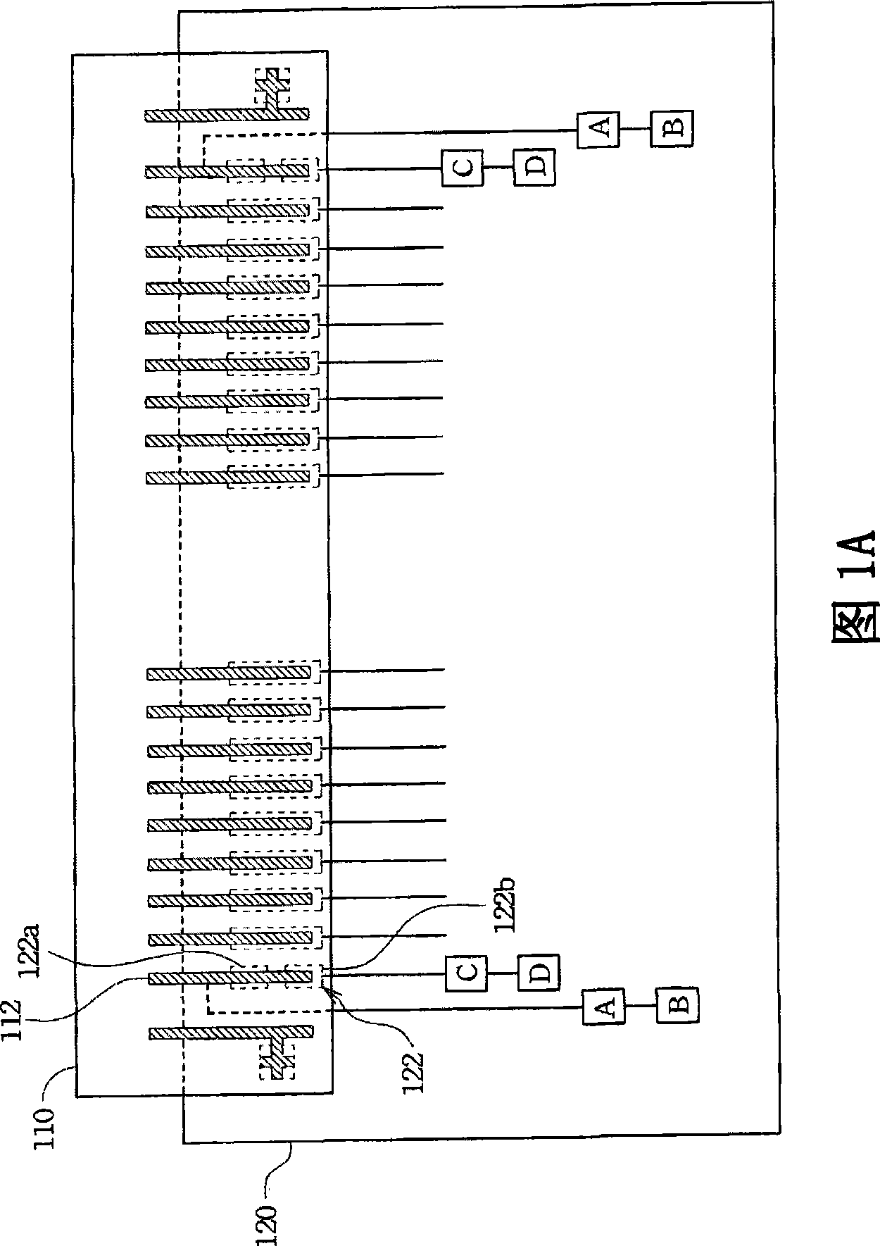
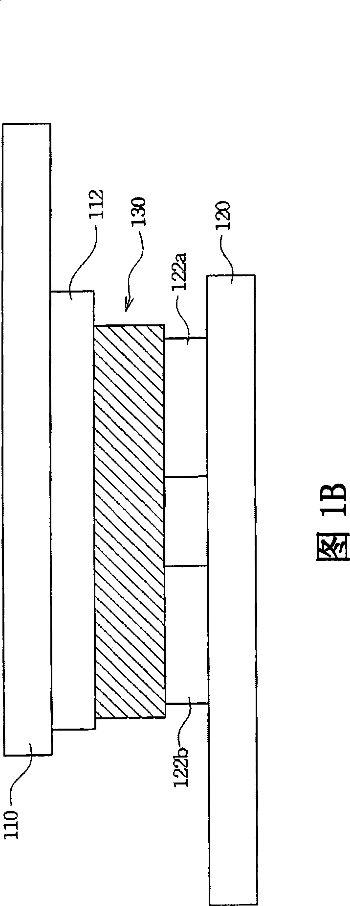
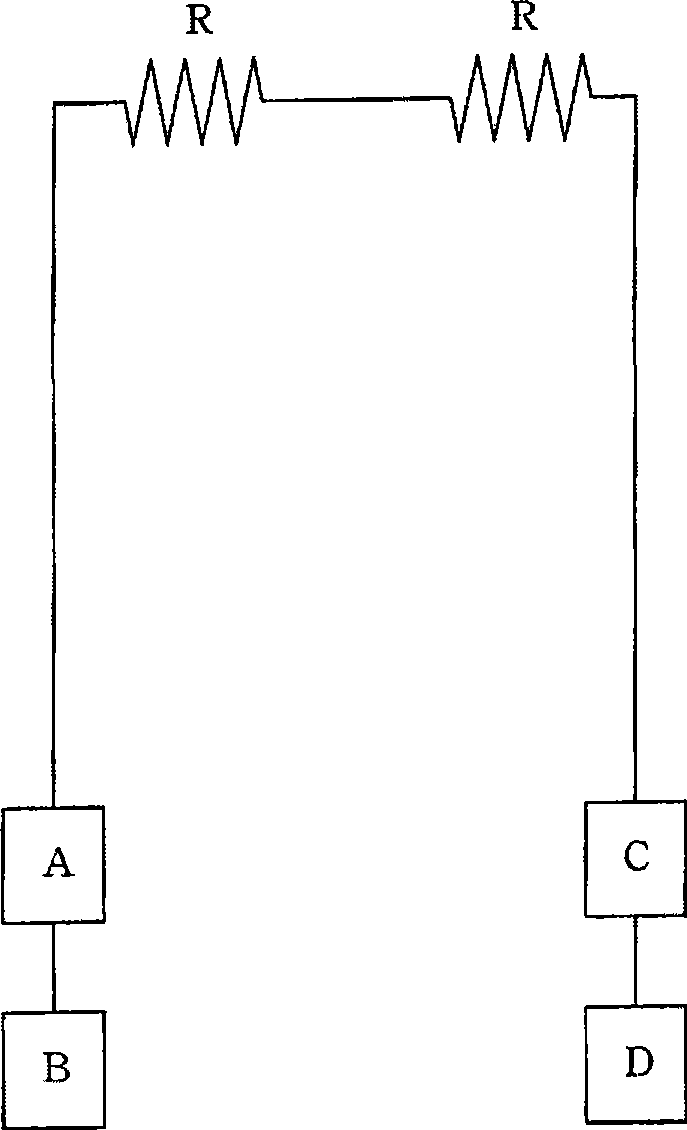
[0030] FIG. 1A is a schematic diagram illustrating the pressing of a circuit board in a liquid crystal display module according to an embodiment of the present invention. The liquid crystal display module includes a flexible circuit board (FPC) 110 and a printed circuit board (PCB) 120. The flexible circuit board 110 is provided with a first wire 112, and the printed circuit board 120 is provided with a second wire 122, and The second wire 122 is electrically connected to the first wire 112. In addition, the printed circuit board 120 may be provided with soldering pads A, B, C, and D, wherein the soldering pad A is electrically connected to the first wire 112, and the soldering pad C is electrically connected to the second wire 122 for supplying with a detection device (such as: A probe or a three-meter or related detection device) is electrically contacted to determine whether the second wire 122 is actually electrically connected to the first wire 112, and the bonding pads B and...


PUM


Abstract

An LCD module and a measuring method for the contact impedance between the circuit boards are provided. The LCD module includes a flexible circuit board, a printed circuit board, a first soldering and a second soldering pad. The flexible circuit board has a first conducting wire. The printed circuit board has the second conducting wire. The second conducting wire electrically connects with the first conducting wire. The first soldering pad electrically connects with the first conducting wire and the second soldering pad electrically connects with the second conducting wire. The first soldering pad and the second soldering pad are contacted for power supply to determine whether the second conducting wire electrically connects with the first conducting wire.

Description

Technical field [0001] The invention relates to a liquid crystal display module and a method for measuring the contact impedance between circuit boards, and more particularly to a structure for measuring the contact impedance between circuit boards in a liquid crystal display module. Background technique [0002] Generally, when making liquid crystal display modules, the printed circuit board (PCB) must be tightly pressed with the flexible printed circuit board (Flexible PrintCircuit; FPC) through conductive glue (such as: anisotropic conductive glue, referred to as ACF glue) , So that the signal can be smoothly transmitted between the printed circuit board and the flexible circuit board. [0003] However, it is known that the method of judging whether the two circuit boards are actually pressed together is only judged by the indentation between them or the amount of glue overflow, so the judgment result is often inaccurate. In addition, since the determination of the indentation...

Claims


Application Information

Patent Timeline
IPC IPC(8): G02F1/13G01R27/02
Inventor 罗日郎范咏达
Owner AU OPTRONICS CORP
Why Eureka
Try Eureka