Outer frame of backlight module unit

A technology of backlight module and outer frame, applied in optics, nonlinear optics, components of lighting devices, etc., can solve the problems of up and down displacement of optical film, increase manufacturing cost, operator fatigue, etc., and achieve easy assembly and The effect of disassembly, improving product quality and reducing operating time

Inactive Publication Date: 2009-05-27
CORETRONIC (SUZHOU) CO LTD
View PDF0 Cites 16 Cited by
  • Summary
  • Abstract
  • Description
  • Claims
  • Application Information

AI Technical Summary

Problems solved by technology

[0005] In addition, in order to ensure that the entire clamping structure is compact and fit in place, the hook-type clamping structure often designs the matching size of the hook on the backplane and the square hole of the plastic frame to be relatively compact, which will make it very difficult for the operator to disassemble. The entire engaging structure needs to be raised, which increases the complexity of the operation and is easy to cause fatigue to the operator. If the operation is not careful, it will cause the optical film (Film) of the display to shift up and down or collide and scratch the screen. Reduce production line yield and increase manufacturing costs

Method used


Image

  • Outer frame of backlight module unit
  • Outer frame of backlight module unit
  • Outer frame of backlight module unit

Examples


Embodiment Construction

[0015] The directional terms mentioned in the following embodiments, such as: up, down, left, right, front or back, etc., are only directions referring to the attached drawings. Accordingly, the directional terms are used to illustrate and not to limit the invention.

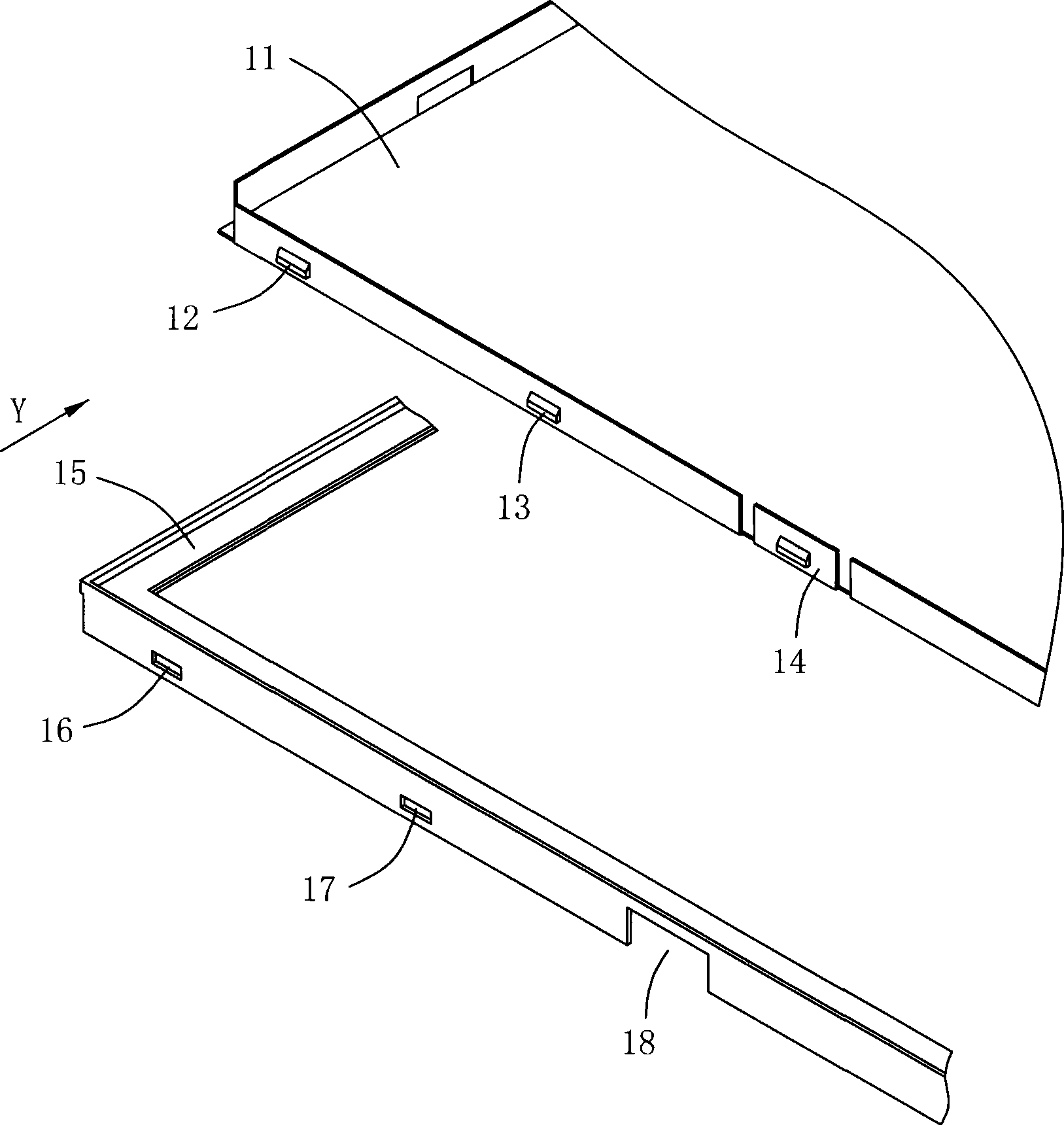
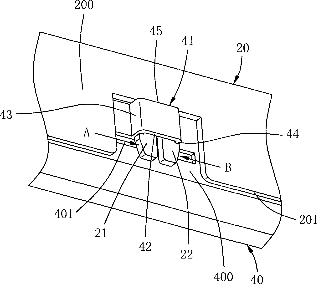
[0016] Please refer to figure 2 , image 3 As shown in FIG. 4 , according to the present invention, an outer frame of a backlight module is provided, which includes a plastic frame (first frame) 20 and a backplane (second frame) 40 . The plastic frame 20 has at least one first hook 21 and one second hook 22, and the backboard 40 has at least one buckle portion 41, the first hook 21 and the second hook 22 can be connected with the buckle portion 41 of the backboard. Interposed and matched with each other to achieve the purpose of fixing the plastic frame 20 and the back plate 40 .

[0017] The plastic frame 20 is made of plastic material. The plastic frame 20 has a first folded edge 200 and at least one firs...


PUM


Abstract

The invention discloses an outer frame of a backlight module, comprising a first frame and a second frame. The first frame is provided with a first edgefold and a first opening. The first edgefold has a bottom edge, a first hook and a second hook. The first opening is concavely arranged to the inside of the first edgefold from the bottom edge. The first hook and the second hook extend towards the bottom edge and extend into the first opening. The second frame is provided with a second edgefold and a second opening arranged on the second edgefold. The second edgefold has a lock portion above the second opening. The lock portion has a top wall, a first side wall and a second side wall. The first side wall and the second side wall are arranged oppositely and extend upwards from the second edgefold. The top wall is connected with the first side wall and the second side wall and arranged above the second opening. The first hook and the second hook are respectively matched with the first side wall and the second side wall.

Description

【Technical field】 [0001] The invention relates to an outer frame of a backlight module, in particular to an outer frame of a detachable backlight module. 【Background technique】 [0002] The outer frame of the backlight module usually includes a plastic frame and a back plate, and the plastic frame of the back light module outer frame and the back plate are processed to form an engaging structure that can be buckled with each other. In this way, the back light module can be fixed internal materials. Therefore, whether the design of the outer frame of the backlight module is easy to assemble and disassemble and whether the fixing method is good will seriously affect the yield rate of finished products and the production speed. [0003] The outer frame of the existing backlight module is mostly designed as an external hook-type positioning. figure 1 shows a three-dimensional structure schematic diagram of an existing outer snap-hook type plastic frame and a backplane engaging...

Claims


Application Information

Patent Timeline
Patent Type & Authority Applications(China)
IPC IPC(8): G02F1/13357F21V21/00G02F1/1335
Inventor 李鹃
Owner CORETRONIC (SUZHOU) CO LTD
Why Eureka
Try Eureka