
Permanent magnet generator with adjustable voltage

A permanent magnet generator, voltage technology, applied in the direction of controlling generators, synchronous motors with static armatures and rotating magnets, electrical components, etc., can solve the problems of high failure rate, complex structure, high cost, and achieve air gap The effect of small gap, wide application range and high concentricity

Inactive Publication Date: 2011-11-09
王光顺
View PDF0 Cites 0 Cited by
  • Summary
  • Abstract
  • Description
  • Claims
  • Application Information

AI Technical Summary

Problems solved by technology

[0002] In order to meet the requirements of grid-connected power generation, the permanent magnet generator needs to be able to adjust the output voltage with the fluctuation of the grid voltage or the change of the reactive load requirement. Now the rectification-inversion method is generally used to electronically adjust the output voltage. Due to the complex structure and the failure rate High cost and high cost have become a major obstacle for permanent magnet generators to be connected to the grid for power generation

Method used


Image

  • Permanent magnet generator with adjustable voltage
  • Permanent magnet generator with adjustable voltage
  • Permanent magnet generator with adjustable voltage

Examples


Embodiment Construction

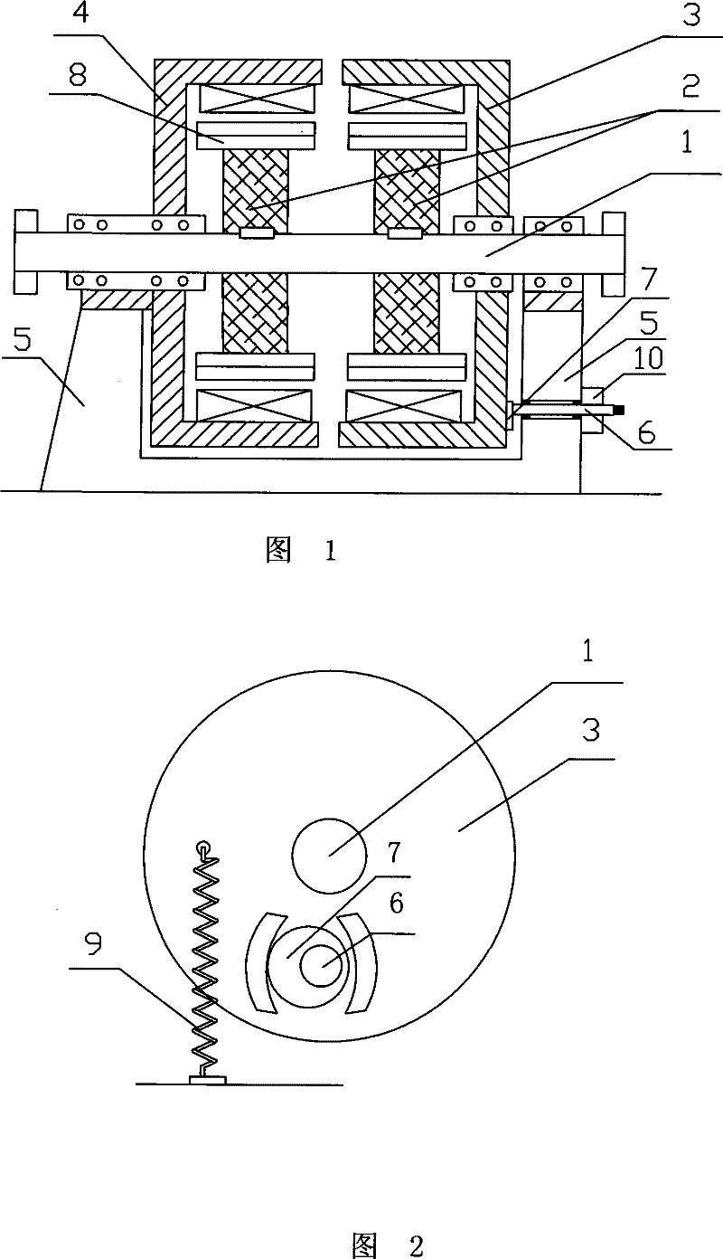
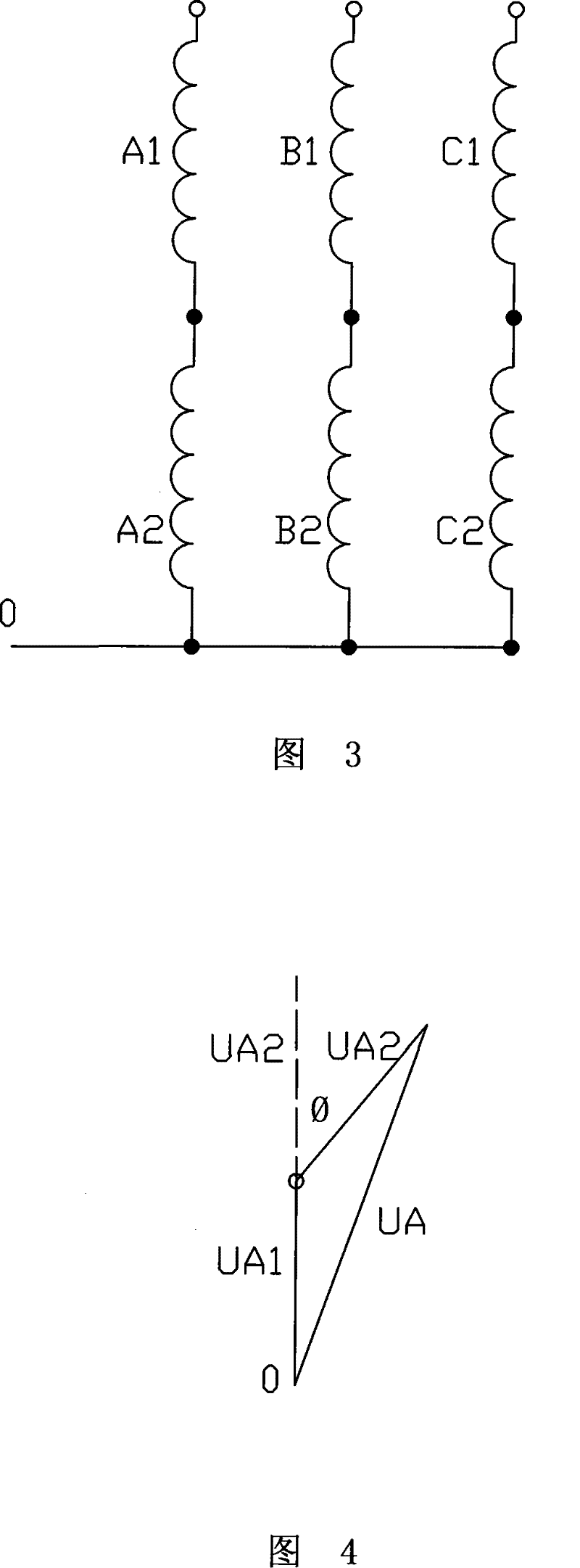
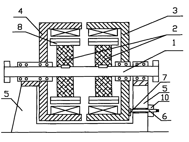
[0018] Such as figure 1 As shown, an adjustable voltage permanent magnet generator according to the present invention includes a main shaft 1 , a rotor 2 fixedly installed on the main shaft 1 , and a stator surrounding the rotor 2 . The rotor 2 is fixedly installed on the main shaft 1 through a flat key, and can be in the form of a large rotor or two small rotors respectively. In this embodiment, two rotors with the same shape and size are installed side by side on the main shaft 1. The permanent magnet 8 is fixedly mounted on the rotor 2 . The stator is installed on the main shaft 1 through bearings, and the stator at least includes a fixed stator 4 and an adjustable stator 3 . This embodiment adopts a fixed stator 4 and an adjustable stator 3, and the fixed stator coils A1, B1, C1 and adjustable stator coils A2, B2, C2 are respectively installed on the fixed stator 4 and the adjustable stator 3. Such as image 3 As shown, the phase lines of the fixed stator coils A1, B1, ...


PUM


Abstract

The invention relates to a generator, in particular to an adjustable voltage permanent-magnet generator, which comprises a main shaft, a rotor fixedly arranged on the main shaft, and stators arranged around the rotor. The rotor is fixedly arranged on the main shaft, a permanent magnet is fixedly arranged on the rotor, the stators are arranged on the main shaft through a bearing, the stators at least comprise a fixed stator and an adjustable stator on which a fixed stator coil and an adjustable stator coil are arranged respectively, phase lines of the fixed stator coil and the adjustable stator coil are correspondingly connected in series respectively, the fixed stator is fixedly connected with a generator bracket, the adjustable stator is connected to the generator bracket through a spring, and the adjustable stator is also provided with a deflection adjusting mechanism. The generator saves a rectification-inversion device in a parallel network of the permanent-magnet generator, has adjustable output voltage, lowers manufacturing cost greatly, and improves reliability of products.

Description

technical field [0001] The invention relates to a generator, in particular to an adjustable voltage permanent magnet generator. Background technique [0002] In order to meet the requirements of grid-connected power generation, the permanent magnet generator needs to be able to adjust the output voltage with the fluctuation of the grid voltage or the change of the reactive load requirement. Now the rectification-inversion method is generally used to electronically adjust the output voltage. Due to the complex structure and the failure rate High cost and high cost have become a major obstacle for permanent magnet generators to be connected to the grid for power generation. Contents of the invention [0003] The purpose of the present invention is to provide an adjustable voltage permanent magnet generator which has a simple structure, can be directly connected to the grid, and can change the output voltage without a rectifier-inversion device. [0004] To achieve the above...

Claims


Application Information

Patent Timeline
Patent Type & Authority Patents(China)
IPC IPC(8): H02K16/00H02K16/04H02K7/12H02K21/12H02P9/00
Inventor 王光顺
Owner 王光顺
Learn More