A position and angle adjustment device for T-type welding
What is AI technical title?
AI technical title is built by Patsnap AI team. It summarizes the technical point description of the patent document.
An angle adjustment device and welding plate technology, which is applied in welding equipment, auxiliary equipment, auxiliary welding equipment, etc., can solve the problems of repeatable positioning, batch welding manufacturing, difficulty in ensuring the accuracy of welded joints, and difficulty in ensuring gap accuracy, etc. problems, to achieve the effect of improving the quality and efficiency of T-shaped welding, novel structure, and ensuring positioning accuracy
Active Publication Date: 2021-05-14
CENT SOUTH UNIV
View PDF5 Cites 0 Cited by
Summary
Abstract
Description
Claims
Application Information
AI Technical Summary
This helps you quickly interpret patents by identifying the three key elements:
Problems solved by technology
Method used
Benefits of technology
Problems solved by technology
In the actual welding process, the welding position and angle between the welding plates often need to be determined after multiple adjustments by means of measurement, scribing tools, etc., which makes the operation process very complicated, and it is difficult to ensure the accuracy requirements of the welded joints
In addition, the gap adjustment process of T-welded welding plates needs to be determined by tools such as feeler gauges, but it is necessary to consider the removal of the feeler gauges and the wear of the feeler gauges during use, resulting in the gap accuracy is often difficult to guarantee; between the welded plates Under the condition that the welding position, angle and gap cannot be guaranteed, it is difficult for the T-shaped welding process to meet the requirements of repeatable positioning and batch welding manufacturing
Method used
Image
Click on the blue label to locate the original text in one second.
Reading with bidirectional positioning of images and text.
Examples
Embodiment 1
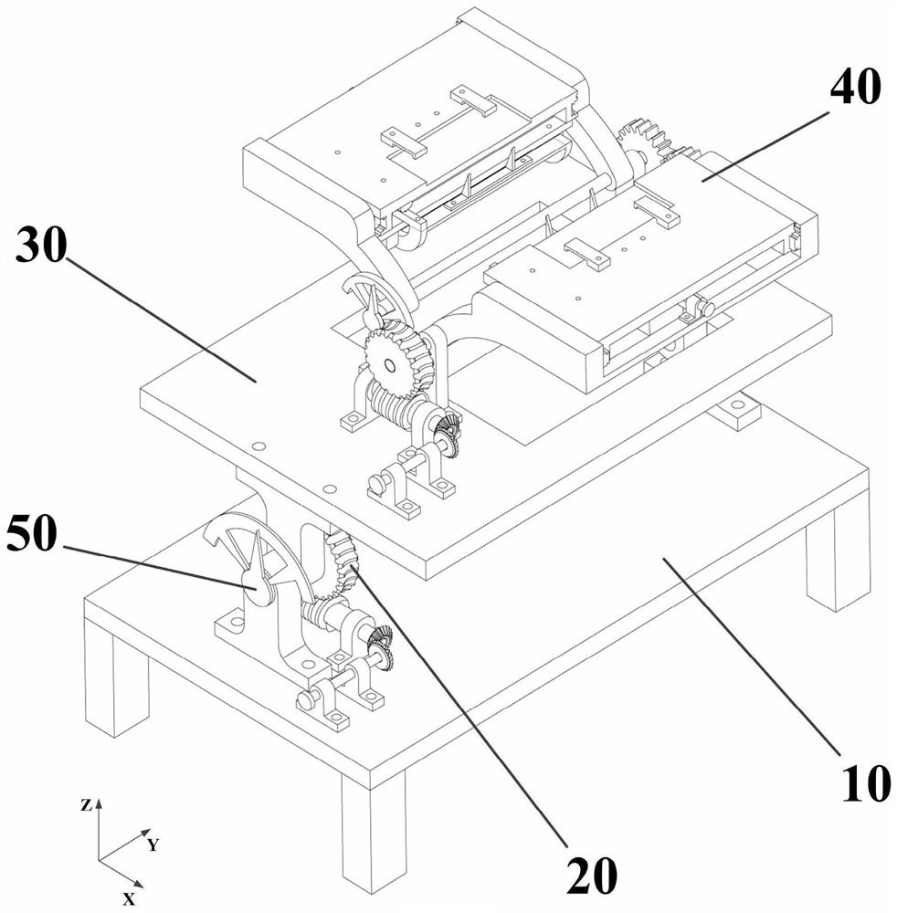
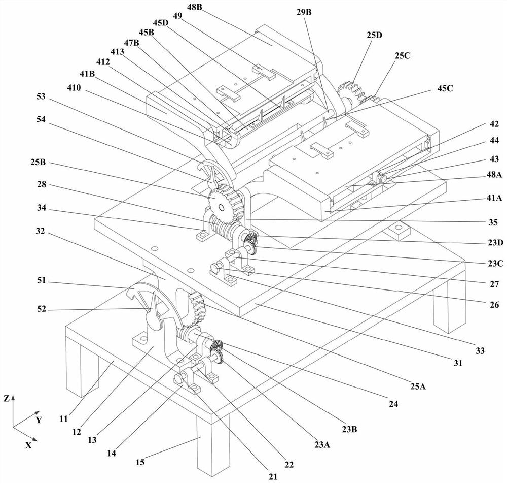
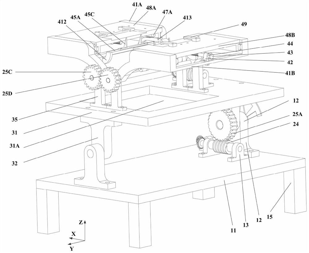
[0032] like figure 1 , figure 2 As shown, the device of the present invention includes a base assembly 10, a transmission mechanism 20, a fixing assembly 30, a positioning mechanism 40 and an indicating assembly 50,
[0033] A. The base assembly 10 includes a base plate 11, a long base plate support 12, a base plate middle support 13, a base plate short support 14 and a support rod 15, and the base plate long support 12, base plate middle support 13 and base plate short support 14 are located on the base plate 11 On the surface, the support rods 15 are arranged at the four corners of the bottom surface of the bottom plate 11, for supporting the bottom plate 11 and increasing the distance between the bottom plate 11 and the ground;
[0034] B, the transmission mechanism 20 includes the first drive rod 22, the first worm 24, the first worm wheel 25A, the second drive rod 27, the second worm 28, the second worm wheel 25B, the front gear shaft 29A, the rear gear shaft 29B, the f...
PUM
Abstract
A position and angle adjustment device for T-shaped welding belongs to a welding position and angle adjustment device, which solves the problem that it is difficult to accurately adjust the welding position, angle and gap existing in the T-shaped welding positioning of the existing welding plate. The present invention includes a base assembly, a transmission mechanism, a fixing assembly, a positioning mechanism and an indicating assembly. The base assembly includes a bottom plate and a bottom support; Support, fixed plate, positioning plate support; positioning mechanism includes front and rear positioning plate, front and rear positioning slide plate, slide plate support, sliding screw rod, sliding screw rod support, driving rod, front and rear pressure rod, front and rear positioning bar ; The indication component includes a welding angle pointer, a welding angle scale, a positioning angle pointer, a positioning angle scale, a positioning displacement pointer, and a positioning displacement scale. The invention is simple and novel, easy to adjust and operate, less affected by the processing environment, can ensure the welding position, angle and gap positioning accuracy in the T-shaped welding of the welding plate, can improve the welding efficiency and quality, and is suitable for various welding methods such as laser welding.
Description
technical field [0001] The invention belongs to a welding position angle adjustment device, in particular to a position and angle adjustment device for T-shaped welding. Background technique [0002] T-welding is a common connection method between various materials. In the T-shaped welding process, it is necessary to determine the welding position, angle and gap between the welding plates. In the actual welding process, the welding position and angle between the welding plates often need to be determined after multiple adjustments by means of measurement and scribing tools, which makes the operation process very complicated and it is difficult to ensure the accuracy requirements of the welded joints. In addition, the gap adjustment process of T-welded welding plates needs to be determined by tools such as feeler gauges, but it is necessary to consider the removal of the feeler gauges and the wear of the feeler gauges during use, resulting in the gap accuracy is often diffic...
Claims
Application Information
Patent Timeline
Application Date:The date an application was filed.
Publication Date:The date a patent or application was officially published.
First Publication Date:The earliest publication date of a patent with the same application number.
Issue Date:Publication date of the patent grant document.
PCT Entry Date:The Entry date of PCT National Phase.
Estimated Expiry Date:The statutory expiry date of a patent right according to the Patent Law, and it is the longest term of protection that the patent right can achieve without the termination of the patent right due to other reasons(Term extension factor has been taken into account ).
Invalid Date:Actual expiry date is based on effective date or publication date of legal transaction data of invalid patent.

