Device and method for selectively controlling the utility of a taget

A technology of target equipment and equipment, applied in digital transmission systems, secure communication devices, electrical components, etc., can solve the problem of not falling into the hands of the enemy, and achieve the effect of flexible sales accounts and less interference

Inactive Publication Date: 2009-05-27
克斯特无线电公司
View PDF3 Cites 4 Cited by
  • Summary
  • Abstract
  • Description
  • Claims
  • Application Information

AI Technical Summary

Problems solved by technology

these weapons and transmissions must be rapidly deployable and usable, but must also be sufficiently con

Method used


Image

  • Device and method for selectively controlling the utility of a taget
  • Device and method for selectively controlling the utility of a taget
  • Device and method for selectively controlling the utility of a taget

Examples


example 4

[0092] In some cases, it is desirable to mass-produce an object (e.g., a computer), package it for shipment, and then test each option (e.g., preloaded software or content, or hardware features) at a manufacturing facility or at a retail point of sale. ) to activate or enter preferences (eg, user or retailer name, configuration information, etc.). An RFA device configured to receive and output multiple data elements, such as a password or key to decrypt preloaded software, may be used for this purpose. For certain types of objects, it may be desirable to activate multiple subassemblies within a single object in order to deter theft of object components. An example is a laptop computer containing several valuable subassemblies such as a hard drive, LCD display, CPU, CD drive, etc. In one example, each subassembly may have its own internal RFA device and be activated by an activation signal to each assembly. exist Figure 15 Another example 400 of how multiple subassemblies m...


PUM


Abstract

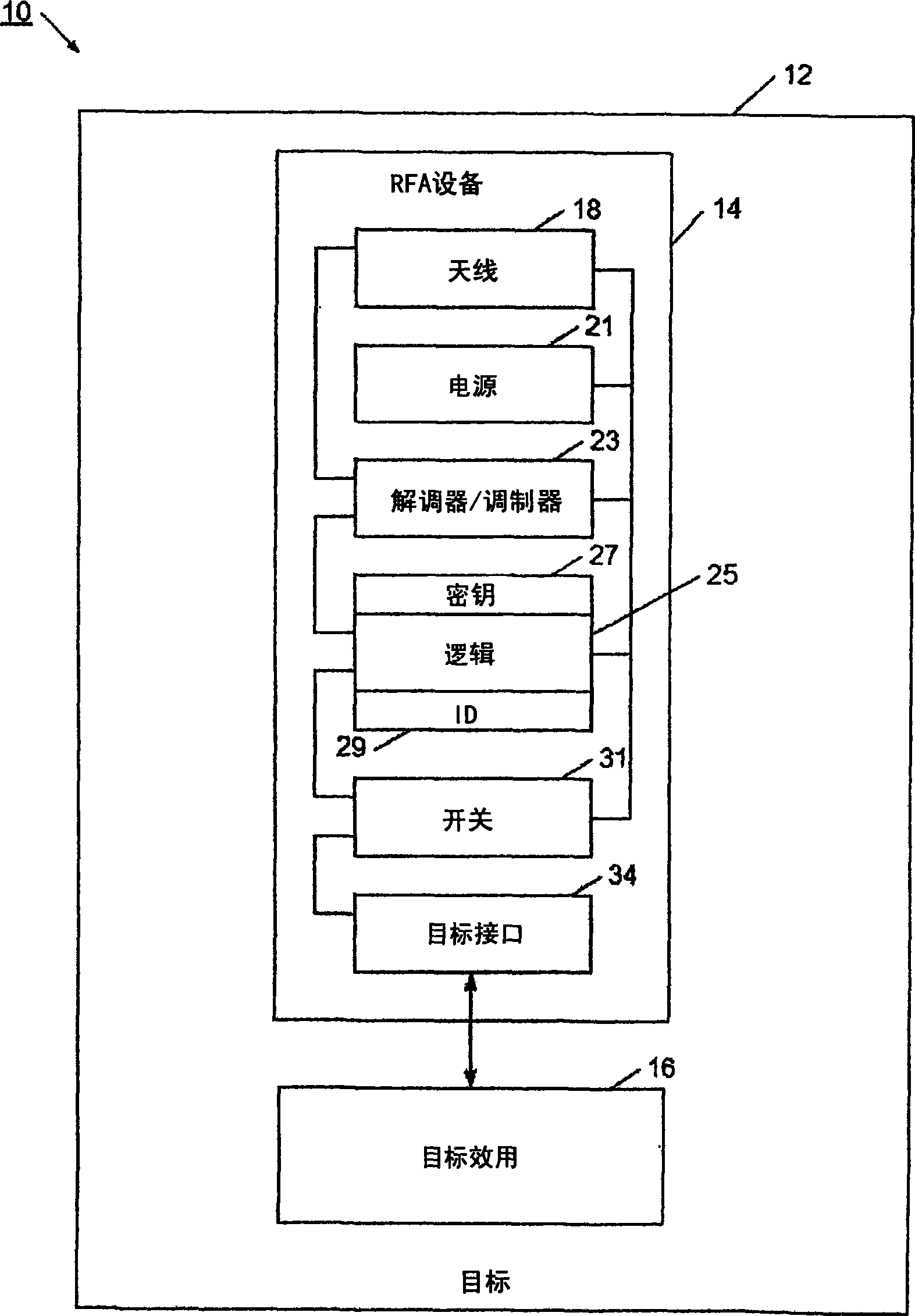
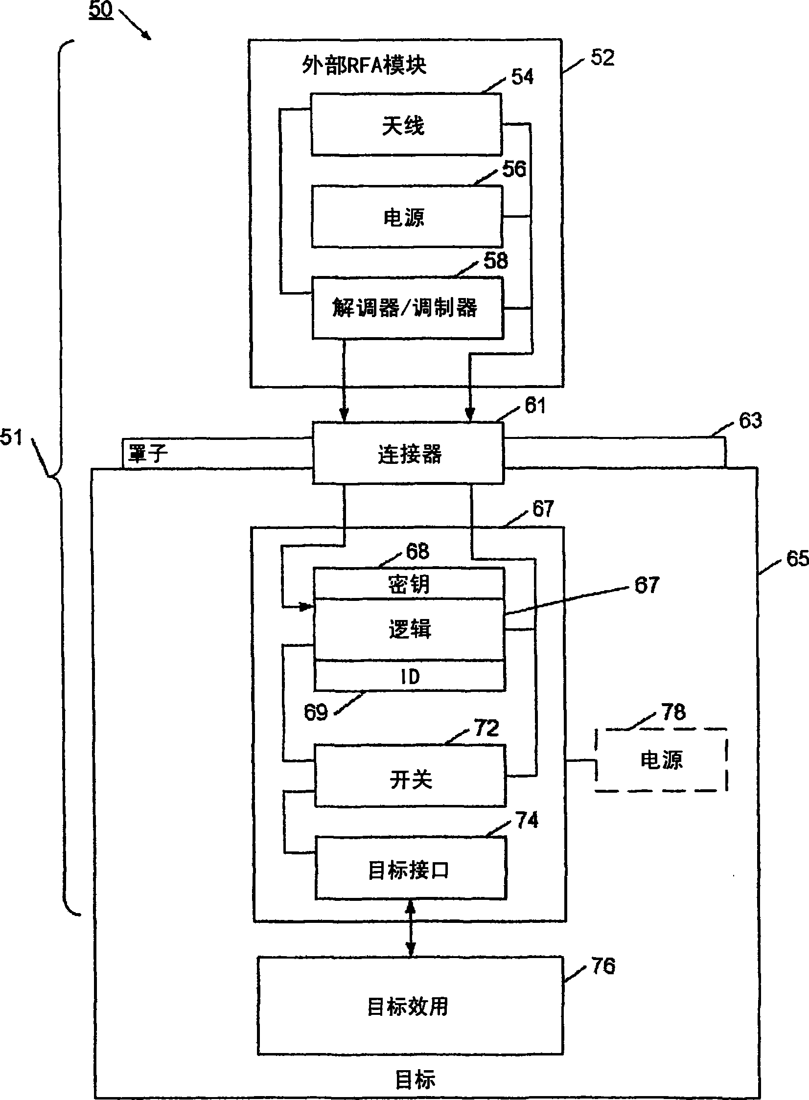
A radio frequency controller device enables the utility of a target to be controlled using an RF communication. The radio frequency controller device has a switch that is set to a defined state responsive to the RF communication. More particularly, conditional logic circuitry uses the RF communication to determine if the target's utility should be changed, and sets the state of the switch accordingly. The radio frequency controller device also has a target interface that allows the target to determine the state of the switch, and based on the state of the switch, a different utility will be available for the target. The radio frequency controller device also has an antenna for the RF communication, as well as a demodulator/modulator circuit. When used to control the utility of an electrical or electronic device, the radio frequency controller device has a low-power circuit portion that is used to set the state of the switch responsive to the RF communication, and also has a full power circuit portion that communicates with the target. In this way, the state of the switch may be set when the target is in a power-off condition, and the target is able to determine the state of the switch when the target is activated.

Description

[0001] related application [0002] This patent application claims priority to U.S. Provisional Patent Application 60 / 633,971, filed December 7, 2004, and entitled "A Method and Means of RF Activation of a Target"; Priority to U.S. Provisional Patent Application 60 / 654,384, "Method and Means of RF Activation of a Target"; U.S. Patent Application 11 / 259,578, filed October 26, 2005, entitled "Method and System for Selectively Controlling the Utility a Target" and U.S. Patent Application 11 / 259,185, filed October 26, 2005, entitled "Method and Network for Selectively Controlling the Utility a Target," all of which are hereby incorporated by reference as if in their entirety mentioned. This application also relates to U.S. Patent Application No. _______ of the common application filed by _____________ and titled “____________________”; and U.S. Patent Application No. ______________ and titled “______________________” filed by ___________________, which are also incorporated herein ...

Claims


Application Information

Patent Timeline
IPC IPC(8): H04L9/00
Inventor P·阿特金森R·S·科内罗
Owner 克斯特无线电公司
Why Eureka
Try Eureka